

Table Of Contents
Contents of Articles
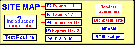
main links
projects:
- PIC LAB-1
- Intro-top
- Intro-bottom
- Test Routine
- PIC Instructions
- HEX Values
- All expt files
- Experiments 1 to 3
- Experiments 4 to 6
- Experiments 7 to 11a
- Experiments 11b to 12
- 21 Matches
- Rock Paper Scissors
- Readers Experiments
Extra Pages
- Index
- Piezo
- Nitinol Wire
- Going Further
- 3-Digit Counter & AtoD
- Library of Routines
- Copy & Save Routines
- Timing and Delays
- Adding extra In/Out
- Advanced Programming
Tests
EXPERIMENT 4
Counting on the 7-segment display
This experiment uses the push-button to increment the count on the 7-segment display. The count-value is stored in a file and this value is incremented by the program each time the push button is pressed. The count-value is used to look-up a table to pick up the display-value for the 7-segment display.
Additional experiments on the website include a count-down routine, a 00 to 99 counter using a single display and others.
The Table: The first value in a table is accessed when the Program Counter has an addition of “0” because it naturally increments to the next location in memory. In the routines below, the number if items in the table are counted and used to determine “end of table.” The reason is the jump-value is incremented before it is compared.
     ;Expt4.asm
     ;Project: Counting on 7-segment display
List P = 16F84
#include <p16F84.inc>
__CONFIG 1Bh ;_CP_OFF & _PWRTE_ON & _WDT_OFF & _RC_OSC
        ORG 0           ;This is the start of memory for the program.
SetUp   BSF 03,5        ;Go to Bank 1
        CLRF 06         ;Make all port B output
        MOVLW 01        ;Load W with 0000 0001
        MOVWF 05        ;Make RA0 input
        BCF 03,5        ;Go to Bank 0 - the program memory area.
        MOVLW 3Fh       ;
        MOVWF 06        ;Put "0" on display at reset
        CLRF 1E         ;Clear the count file
        CLRF 1F         ;Clear the button-press file
        GOTO Main

Table   ADDWF 02h,1     ;Add W to the Program Counter to create a jump.
        NOP             ; format= gfedcba
        RETLW 06h       ;1 If any table value has a leading letter, it must be
        RETLW 5Bh       ;2  preceded with a "0."  E.g: 0A3h, 0FFh, 0CCh
        RETLW 4Fh       ;3
        RETLW 66h       ;4
        RETLW 6Dh       ;5
        RETLW 7Dh       ;6
        RETLW 07h       ;7
        RETLW 7Fh       ;8
        RETLW 6Fh       ;9
        RETLW 3Fh       ;0


Delay   MOVLW 0A        ;Create 1mS debounce delay
        MOVWF 1B
Del1    NOP
        DECFSZ 1A,1
        GOTO Del1
        DECFSZ 1B,1
        GOTO Del1
        RETURN

Main    Main CLRF 1E    ;1E holds the count-value. Next increment: file=1
Main1   BTFSS 05,0      ;Test the input line on port A
        GOTO Main2      ;Button not pressed
        CALL Delay      ;Debounce the button
        BTFSC 1F,0      ;Button pressed first time?
        GOTO Main1      ;Button already pressed
        INCF 1E,1       ;First time button pressed. Increment count.
        MOVLW 0B        ;Has count reached eleven?
        XORWF 1E,0      ;Compare file 1E with eleven
        BTFSC 03,2      ;Check the zero flag in Status file
        GOTO Main       ;
        MOVF 1E,0       ;Copy count into W
        CALL Table      ;W will return with display-value
        MOVWF 06        ;Output display value
        BSF 1F,0        ;Set button-press flag
        GOTO Main1      ;Loop Main1
Main2   CALL Delay      ;Button not pressed. Call Delay
        BCF 1F,0        ;Clear button-press flag
        GOTO Main1      ;Loop Main1

        END             ;Tells assembler end of program
EXPERIMENT 4a
Binary Counting
This experiment produces a binary count on the 8 LEDs. The output will always show the content of file 06. File 06 can be incremented, decremented, and shifted, etc just like any of the other files. The program increments the count in file 06 and shows it for 0.5sec, before incrementing to the next value. A files will show values in binary, from 00 to 127, making a total of 128 for each cycle of the file.
     ;Expt4a.asm
     ;Project: Binary Counting
List P = 16F84
#include <p16F84.inc>
__CONFIG 1Bh ;_CP_OFF & _PWRTE_ON & _WDT_OFF & _RC_OSC

        ORG 0       ;This is the start of memory for the program.
SetUp   BSF 03,5    ;Go to Bank 1
        CLRF 06     ;Make all port B output
        BCF 03,5    ;Go to Bank 0 - the program memory area.
        CLRF 06     ;Turn off all LEDs
        GOTO Main

Delay   NOP         ;Create approx 250mS delay
        DECFSZ 1A,1
        GOTO Delay
        DECFSZ 1B,1
        GOTO Delay
        RETURN

Main    CALL Delay  ;Show LEDs for 250mS
        CALL Delay  ;Show LEDs for 250mS
        INCF 06     ;Increment the count in file 6
        GOTO Main   ;Loop

        END         ;Tells assembler end of program
EXPERIMENT 4b
Binary Counting - up/down
This experiment counts up and down in binary. A push button reverses the count.
It is very interesting to see how a file increments and decrements. This will help you understand binary numbers. The numbers increment at 4 counts per second. At the same time you will see all combinations of segments on the 7-segment display.
     ;Expt4b.asm
     ;Project: Binary Counting up/down
List P = 16F84
#include <p16F84.inc>
__CONFIG 1Bh ;_CP_OFF & _PWRTE_ON & _WDT_OFF & _RC_OSC

        ORG 0       ;This is the start of memory for the program.
SetUp   BSF 03,5    ;Go to Bank 1
        MOVLW 01    ;Load W with 0000 0001
        MOVWF 05    ;Make RA0 input
        CLRF 06     ;Make all port B output
        BCF 03,5    ;Go to Bank 0 - the program memory area.
        CLRF 06     ;Turn off all LEDs
        CLRF 1F     ;Clear the button-press file
        GOTO Main

Delay   NOP         ;Create approx 250mS delay
        DECFSZ 1A,1
        GOTO Delay
        DECFSZ 1B,1
        GOTO Delay
        RETURN

Main    CALL Delay  ;Show LEDs for 250mS
        INCF 06,1   ;Increment the count in file 6
        BTFSS 05,0  ;Push-button pressed?
        GOTO MainA  ;No
        BTFSS 1F,0  ;Test button-press flag
        GOTO Main2  ;First pass for button?
        BSF 1F,0
        GOTO Main
MainA   BCF 1F,0
        GOTO Main

Main2   CALL Delay  ;Show LEDs for 250mS
        DECF 06     ;Decrement the count in file 6
        BTFSS 05,0  ;Push-button pressed?
        GOTO MainB  ;No
        BTFSS 1F,0  ;Test button-press flag
        GOTO Main   ;First pass for button?
        BSF 1F,0
        GOTO Main2
MainB   BCF 1F,0
        GOTO Main2

        END         ;Tells assembler end of program
EXPERIMENT 4c
Producing letters on the 7-segment display
This experiment shows letters of the alphabet on the 7-segment display. Almost all the letters can be displayed except k, m, v, w, x, z. Sometimes only a capital or small can be displayed and this results in a mixture for some words. However it is nearly always possible to use words that can be easily displayed. To produce a word, the letters are flashed on the display for a short period of time with a brief blank between each letter. This allows doubles to be displayed, especially double numbers for telephone numbers etc. The following routine automatically displays all the letters. Experiment 4 has the hex values for the numbers 0-9. Some of the other difficult letters can be created on the display and if readers accept them as readable, they will be added to the list.
The program displays each letter for 0.75sec and turns the display off for 0.25sec. No input button is required for the execution of the program.
     ;Expt4c.asm
     ;Project: Displaying letters
List P = 16F84
#include <p16F84.inc>
__CONFIG 1Bh ;_CP_OFF & _PWRTE_ON & _WDT_OFF & _RC_OSC

        ORG 0           ;This is the start of memory for the program.
SetUp   BSF 03,5        ;Go to Bank 1
        CLRF 06         ;Make all port B output
        BCF 03,5        ;Go to Bank 0 - the program memory area.
        GOTO Main


Table   ADDWF 02h,1     ;Add W to the Program Counter to create a jump.
        RETLW 77h       ;A This is jump=0 location.   format= gfedcba
        RETLW 7Ch       ;b
        RETLW 39h       ;C
        RETLW 5Eh       ;d
        RETLW 79h       ;E
        RETLW 71h       ;F
        RETLW 6Fh       ;g
        RETLW 76h       ;H
        RETLW 06h       ;I
        RETLW 1Eh       ;J
        RETLW 38h       ;L
        RETLW 37h       ;N
        RETLW 3Fh       ;O
        RETLW 73h       ;P
        RETLW 67h       ;q
        RETLW 50h       ;r
        RETLW 6Dh       ;S
        RETLW 78h       ;t
        RETLW 3Eh       ;U
        RETLW 6Eh       ;y

Delay   NOP             ;Create approx 250mS delay
        DECFSZ 1A,1
        GOTO Delay
        DECFSZ 1B,1
        GOTO Delay
        RETURN

Main    CLRF 1E         ;File 1E holds the jump-value for the table
Main1   MOVF 1E,0       ;Copy the jump-value into W
        CALL Table      ;W will return with display-value
        MOVWF 06        ;Output display value
        CALL Delay      ;Display for 0.25sec
        CALL Delay      ;Display for 0.25sec
        CALL Delay      ;Display for 0.25sec
        CLRF 06         ;Clear the display
        CALL Delay      ;Blank the display for 0.25sec
        INCF 1E,1       ;Increment jump-value to look at next table value
        MOVLW 14h       ;The number of table-values (in hex)
        XORWF 1E,0      ;Has the jump-value reached 14h?
        BTFSS 03,2      ;Test the zero bit in the Status register
        GOTO Main1      ;Loop to display next value
        GOTO Main       ;Start again

        END             ;Tells assembler end of program
EXPERIMENT 4d
Displaying WORDS
This experiment shows “PUSH BUttON” on the 7-segment display. The sub-routine is called “Word1” and can be called from Main. You can add this sub-routine to any of your programs. A second word can be created by calling “Word2” etc. If a number of words are needed, the structure of the program can be altered so that a standard word calling routine is used that picks up a word from a table and looks for FF to end the word.
     ;Expt4d.asm
     ;Project: Displaying WORDS
List P = 16F84
#include <p16F84.inc>
__CONFIG 1Bh ;_CP_OFF & _PWRTE_ON & _WDT_OFF & _RC_OSC

        ORG 0           ;This is the start of memory for the program.
SetUp   BSF 03,5        ;Go to Bank 1
        CLRF 06         ;Make all port B output
        BCF 03,5        ;Go to Bank 0 - the program memory area.
        GOTO Main


Table1  ADDWF 02h,1     ;Add W to the Program Counter to create a jump.
        RETLW 73h       ;P This is jump=0 location.   format= gfedcba
        RETLW 3Eh       ;U This is jump=1 location.
        RETLW 6Dh       ;S  This is jump=2 location.
        RETLW 76h       ;H
        RETLW 00h       ;blank
        RETLW 7Ch       ;B
        RETLW 3Eh       ;U
        RETLW 78h       ;t
        RETLW 78h       ;t
        RETLW 3Fh       ;O
        RETLW 37h       ;N
        RETLW 00h       ;blank

Delay   NOP             ;Create approx 250mS delay
        DECFSZ 1A,1
        GOTO Delay
        DECFSZ 1B,1
        GOTO Delay
        RETURN

Word1   MOVF 1E,0       ;Copy the jump-value into W
        CALL Table1     ;W will return with display-value
        MOVWF 06        ;Output display value
        CALL Delay      ;Display for 0.25sec
        CALL Delay      ;Display for 0.25sec
        CALL Delay      ;Display for 0.25sec
        CLRF 06         ;Clear the display
        CALL Delay      ;Show display for 0.25sec
        INCF 1E,1       ;Increment jump-value to look at next table value
        MOVLW 0Ch       ;The number of table-values (in hex)
        XORWF 1E,0      ;Has the jump-value reached 0Ch?
        BTFSS 03,2      ;Test the zero bit in the Status register
        GOTO Word1      ;Loop to display next table-value
        RETURN          ;Start again

Main    CLRF 1E         ;File 1E holds the jump-value for the table
        CALL Word1
        GOTO Main

        END             ;Tells assembler end of program
EXPERIMENT 4e
Push “A” to display a word
This experiment shows “ENtEr” on the 7-segment display, after button “A” is pressed. The experiment shows how to combine two sub-routines. The program is constantly POLLING button “A” and when it is pushed, a flag is set and the micro returns to Main. The flag file is 1F and the flag bit is bit0. In Main, the flag bit is checked and if it is set, the micro goes to Word1 to display “ENtEr,” from Table1.
     ;Expt4e.asm
     ;Project: Push "A" to display a word
List P = 16F84
#include <p16F84.inc>
__CONFIG 1Bh ;_CP_OFF & _PWRTE_ON & _WDT_OFF & _RC_OSC

        ORG 0           ;This is the start of memory for the program.
SetUp   BSF 03,5        ;Go to Bank 1
        CLRF 06         ;Make all port B output
        BCF 03,5        ;Go to Bank 0 - the program memory area.
        CLRF 1F         ;Clear the button-press file
        GOTO Main

Table1  ADDWF 02h,1     ;Add W to the Program Counter to create a jump.
        RETLW 79h       ;E  This is jump=0 location.   format= gfedcba
        RETLW 37h       ;N This is jump=1 location.
        RETLW 78h       ;t   This is jump=2 location.
        RETLW 79h       ;E
        RETLW 50h       ;r
        RETLW 00h       ;blank

Delay   NOP             ;Create approx 250mS delay
        DECFSZ 1A,1
        GOTO Delay
        DECFSZ 1B,1
        GOTO Delay
        RETURN

Sw      BTFSS 05,0      ;Test the push-button input
        RETURN          ;Sw NOT pushed
        BSF 1F,0        ;Switch pushed. Set button flag.
        RETURN

Word1   MOVF 1E,0       ;Copy the jump-value into W
        CALL Table1     ;W will return with display-value
        MOVWF 06        ;Output display value
        CALL Delay      ;Display for 0.25sec
        CALL Delay      ;Display for 0.25sec
        CALL Delay      ;Display for 0.25sec
        CLRF 06         ;Clear the display
        CALL Delay      ;Show display for 0.25sec
        INCF 1E         ;Increment jump-value to look at next table value
        MOVLW 06h       ;The number of table-values (in hex)
        XORWF 1E,0      ;Has the jump-value reached 06h?
        BTFSS 03,2      ;Test the zero bit in the Status register
        GOTO Word1      ;Loop to display next table-value
        RETURN

Main    CLRF 1E         ;File 1E holds the jump-value for the table
        CALL Sw         ;Poll (look at) push-button "A"
        BTFSC 1F,0      ;Has switch been pushed?
        CALL Word1      ;Yes. Display "ENtEr"
        BCF 1F,0        ;Clear button flag
        GOTO Main

        END             ;Tells assembler end of program
EXPERIMENT 5
Creating a tone
This experiment creates a tone. A tone is simply the action of turning on an output, executing a delay, turning off the output, executing a delay, then repeating the sequence.
This action produces a square-wave and the microcontroller activates a driver transistor that drives a piezo diagram to produce the characteristic harsh sound.
The microcontroller can drive a piezo diaphragm directly but we have opted to add a driver transistor so the circuit can also drive a mini speaker, if needed. Place your finger on and around the components to see how the resistance of your finger affects the performance of the circuit. This indicates the sensitive components.
Once you know how to produce a tone, the whole world opens up to sounds, noises, tones and tunes.
     ;Expt5.asm
     ;Project: Creating a tone
List P = 16F84
#include <p16F84.inc>
__CONFIG 1Bh ;_CP_OFF & _PWRTE_ON & _WDT_OFF & _RC_OSC

        ORG 0           ;This is the start of memory for the program.
SetUp   BSF 03,5        ;Go to Bank 1
        CLRF 06         ;Make all port B output
        BCF 03,5        ;Go to Bank 0 - the program memory area.
        CLRF 06         ;Clear outputs of junk
        GOTO Main

Delay   NOP             ;Create 1mS delay
        DECFSZ 1A,1
        GOTO Delay
        RETURN

Main    BSF 06,7        ;Turn on driver transistor
        CALL Delay      ;Create ON time
        BCF 06,7        ;Turn off driver transistor
        CALL Delay      ;Create OFF time
        GOTO Main       ;Loop

        END             ;Tells assembler end of program
EXPERIMENT 6
Creating a tune
This experiment creates a tune. It is an extension of experiment 5.
A sequence of tones is produced by making a table containing a pair of values for each note. The first value produces the time-delay between the high and low of the output and thus creates the frequency of the tone. The second value creates the length of time for the note.
This value is a little bit more complex than first appears.
Suppose we want to reproduce a middle C minum:
The tune “Hey Jude” is played at at speed know as “Allegro.” This has a metronome rate of between 120 and 160. Suppose we choose the centre-value of 140. This is 140 beats per minute and represents the time taken to play a minum or half-note. (A minum is a hollow oval with a plain riser). You may recall, a metronome beats or “clicks” each time it moves to the left and to the right. The time between the “click-click” is 1/140 minute. This gives 430mS for a minum. A Crotchet is a solid oval with a riser and takes 215mS. A Quaver has a flag on the riser and takes 107mS. A semi-quaver has two flags and takes 53mS.
Middle C is 262Hz. From this we know the length of the delay between the high and low output, to produce one cycle.
The other value we need to know is the number of cycles of middle-C in 430mS. The answer is 112.
For each frequency we need to work out the number of cycles for each length of note.
With this we can create a table of values. The program will pick up a pair of values and play the note for the correct duration. The end of the table is assigned FF. The program looks for FF to repeat.
     ;Expt6.asm
     ;Project: Creating a tune
List P = 16F84
#include <p16F84.inc>
__CONFIG 1Bh ;_CP_OFF & _PWRTE_ON & _WDT_OFF & _RC_OSC

        ORG 0           ;This is the start of memory for the program.
SetUp   BSF 03,5        ;Go to Bank 1
        CLRF 06         ;Make all port B output
        BCF 03,5        ;Go to Bank 0 - the program memory area.
        CLRF 06         ;Clear outputs of junk
SetUp1  MOVLW 01
        MOVWF 0Ch
        GOTO Main

Table   ADDWF 02h,1
        RETLW 0A8h      ;duration - 168 loops
        RETLW 5Bh       ;G - 392Hz 1.27mS HIGH,LOW - 91 loops
        RETLW 0FAh      ;duration - 250 loops
        RETLW 6Bh       ;E - 330Hz 1.51mS HIGH,LOW - 107 loops
        RETLW 46h       ;duration - 70 loops
        RETLW 6Bh       ;E - 330Hz
        RETLW 54h       ;duration - 84 loops
        RETLW 5Bh       ;G - 392Hz
        RETLW 5Eh       ;duration - 94 loops
        RETLW 51h       ;A - 440Hz - 1.13mS HIGH,LOW - 81 loops
        RETLW 0FCh      ;duration - 252 loops
        RETLW 7Ah       ;D - 292Hz - 1.71mS HIGH,LOW - 122 loops
        RETLW 0FFh      ;End of table
        RETLW 0FFh      ;End of table

Delay   NOP             ;Create 10uS delay
        NOP
        NOP
        NOP
        NOP
        NOP
        RETURN

Delay2  CALL Delay      ;Create 3mS delay
        DECFSZ 1A,1
        GOTO Delay2
        RETURN

Delay3  NOP             ;250mS delay
        DECFSZ 1A,1
        GOTO Delay3
        DECFSZ 1B,1
        GOTO Delay3
        RETURN

Main    DECF 0C,1       ;Dec jump value to re-look at values
        MOVF 0Ch,0      ;Copy jump-value into W
        CALL Table      ;Return with table-value in W
        MOVWF 0F        ;Length of note into file 0F
        INCF 0Ch,1      ;Increment the table-value
        MOVF 0Ch,0      ;Copy jump-value into W
        CALL Table      ;Return with table-value in W
Main1   MOVWF 0D        ;Frequency of note into file 0D
        MOVWF 0E        ;Frequency of note into file 0E
Main2   BSF 06,7
        CALL Delay      ;Create HIGH time
        DECFSZ 0D,1     ;Each loop = 14uS
        GOTO Main2
Main3   BCF 06,7
        CALL Delay      ;Create LOW time
        DECFSZ 0E,1
        GOTO Main3
        DECFSZ 0F,1     ;Length of note
        GOTO Main1
        BCF 06,7
        CALL Delay2     ;3mS between notes
        CALL Delay2     ;3mS between notes
        CALL Delay2     ;3mS between notes
        INCF 0Ch,1      ;Increment pointer to next value in table
        MOVF 0Ch,0      ;Copy jump-value into W
        CALL Table      ;Return with table-value in W
        MOVWF 10h       ;Put "end of table" into file 10h
        MOVLW 0FFh      ;Check for 'end of table'
        XORWF 10h,0     ;Compare file 10h with FF (result in W)
        BTFSC 03,2      ;Look at Zero flag in status file
        GOTO Main4      ;Start again
        INCF 0Ch,1      ;Increment the table-value
        GOTO Main       ;Go to next note
Main4   CALL Delay3
        CALL Delay3
        CALL Delay3
        GOTO SetUp1

        END             ;Tells assembler end of program
EXPERIMENT 7
Siren Sound*
This experiment creates a Siren sound.
It can be added to an alarm and when played through an 8-watt horn speaker, the output can be ear-shattering.
The program shows how the instructions create a delay between the output being HIGH and LOW, to produce one cycle. When this is repeated, a tone is produced. It is actually a square-wave output. As the delay between the HIGH and LOW is reduced or increased, the tone rises or falls. Additional alarm sounds are described on the website.
     ;Expt7.asm
     ;Project: Siren Sound
List P = 16F84
#include <p16F84.inc>
__CONFIG 1Bh ;_CP_OFF & _PWRTE_ON & _WDT_OFF & _RC_OSC

        ORG 0           ;This is the start of memory for the program.
SetUp   BSF 03,5        ;Go to Bank 1
        CLRF 06         ;Make all port B output
        BCF 03,5        ;Go to Bank 0 - the program memory area.
        CLRF 06         ;Clear display
        GOTO Siren

Siren   MOVLW 80h       ;Number of cycles for each tone
        MOVWF 0Eh
        MOVWF 10h
        MOVLW 50h       ;Number of steps
        MOVWF 0Fh       ;File 0F holds the number of steps
        MOVLW 50h       ;Determines frequency
        MOVWF 0Ch       ;File 0C determines the frequency
Repeat  MOVF 0C,0       ;File 0C is moved to W
        MOVWF 0D        ;W is moved to file 0D for decrementing
On      BSF 06,7        ;Length of HIGH time to Piezo
        DECFSZ 0D,1
        GOTO On
        MOVWF 0Dh       ;W is moved to file 0D again
Off     BCF 06,7        ;Length of LOW time to Piezo
        DECFSZ 0D,1
        GOTO Off
        DECFSZ 10h,1    ;Number of cycles for each tone
        GOTO Repeat
        DECF 0C,1       ;HIGH and LOW is shortened -tone rises
        INCF 0E,1       ;Increase the number of cycles
        MOVF 0E,0       ;File 0E to W
        MOVWF 10h       ;W to file 10h
        DECFSZ 0F,1     ;Number of steps
        GOTO Repeat
        GOTO Siren

        END             ;Tells assembler end of program

Quick Links
Legal Stuff
Social Media