

- CD 4001 Quad NOR gate
- CD 4011 Quad NAND gate
- CD 4013 Dual D Flip Flop
- CD 4014 8-Stage shift register
- CD 4017 Divide by 10
- CD 4020 14-Stage Bin Counter
- CD 4024 7-Stage Binary Count
- CD 4026 7-Segment Driver
- CD 4040 12-Stage Bin Counter
- CD 4049 HEX Inverter
- CD 4060 14-Stage with Osc
- CD 4069 HEX Inverter
- CD 40106 Hex Schmitt Trigger
- CD 4510 BCD up/down Counter
- CD 4511 BCD TO 7-Segment
- LM 324 Quad OP-AMP
- LM 380 4 watt amp
- LM 386 0.5 watt amp
- LM 741 OP-AMP
- OP-AMP List
- Opto Coupler List
- PIC Chip List
- S/mount Diodes/Zeners
- Surface Mount LEDs
- Surface Mount Resistors
- Surface Mount Transistors
- Surface Mount Outlines
- Voltage Regulators
- 40106 Hex Schmitt Trigger
- 555 Timer Chip
- 556 Dual Timer Chip
- 567 Tone Decoder
- 74c14 Hex Schmitt Trigger
Connecting leads to Electroluminescent cable is a delicate operation. The end must be prepared very carefully to prevent fine wires being broken and soldering takes a certain amount of skill.
EL Cable has two conductors. An inner and outer conductor or wire. The outer conducting wire is actually two very fine wires. These must be twisted together to form a single wire. The inner conductor is the thick centre wire. After soldering to these wires, they must be kept separated and insulated from each other. The wiring should also be insulated from the outside environs to prevent accidental contact and also prevent moisture getting into (and onto) the active substrate.
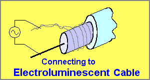
Connecting and AC voltage to the EL Cable
PREPARING THE ENDS OF EL WIRE
Only one end of a length of Electroluminescent cable needs to be prepared for connecting the supply voltage. The other end is called the “But-end” or “dead-end” and must be terminated with a cap or sealed with silicon sealant to prevent moisture “wicking” up the tubing and damaging the phosphors. You must also check the “but-end” (the “cut-off” end) before sealing to make sure the fine outer wires do not touch the inner wire (or are not near it) as the voltage can form a “trace” across the conducting materials and create a path that will “kill” the operation of the cable. Seal the end and you are ready to work on the “active” end.
To prepare the “active” end, the outer “sheath” must be removed to expose two fine wires. This can be done with sharp side-cutters or a blade. By cutting carefully around the outer layer, it can be slid off. Remove about 1.5cm (1/2inch).
To cut the outer layer without damaging the inner layers, the tubing can be bent slightly and cut at the same time.
Stripping tools are also available for the job and are an advantage if a large number of ends need to be prepared.
The fine wires are unwound and twisted together.
Next, the inner wire needs to be exposed. Cut the inner tubing at the 0.5cm mark and slide it off the inner wire.
The inner wire must now be cleaned and scraped with a blade to expose the metal. When this is done, the two conductors can be tinned, ready for the power leads.
When soldering wires to the EL cable, it is important to stagger the connections, so that they never touch.
Solder to the inner wire first, then make sure the outer connection is away from the first connection.
You can complete the joint by sliding a length of heat-shrink tubing over the connections and shrink the tubing with a flame, lighter or hot-air gun. The final result is shown below:
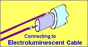
Soldering leads to EL cable
If the two connecting wires are joined together (this is called figure-8 flex or figure-8 wire), the connection will be very strong as the centre wire is very thick and will resist a small amount of “tugging.” However, if the two connecting wires are separate, you must be careful to heat-shrink the joint or join the two connecting wires together so that the outer connection cannot be pulled from its “safe” position. The two solder points cannot be allowed to come close to each other as the voltage will “flash over” and create a low resistance path.
The “dead end” of the EL cable should also be checked to make sure the two electrodes are not touching each other.
When ordering large quantities of a specified length, the ends are terminated with a silicon cap. This creates a water-proof joint and allows the LitELine cable to be used outdoors.

Quick Links
Legal Stuff
Social Media