

Table Of Contents
0-12v DC
0-1Amp (current adjustable)
Power Supply MkII kit from Talking Electronics for $20.00 plus $7.50 postage.
Click [HERE](mailto:colin@elechelp.com?Subject=Buying Power Supply MkII kit $20.00 plus $7.50 postage &Body=Please%20e-mail%20the%20cost%20of Buying Power Supply MkII kit $20.00 plus $7.50 postage by%20air%20mail%20to%20my%20country:**___****%20%20and%20send%20details%20of%20how%20I%20can%20pay%20for%20it.%20My%20name%20is:____) for details.**
This is the cheapest, safest Power Supply you can get.
It will deliver 0-12v at 1amp and you can limit the current to a few milliamp so you will not damage a project you are designing.
It has 14v at 5 amp - called an AUXILIARY OUTPUT - that connects directly to 4 cells and you need to be careful as the Li-ion cells are capable of delivering up to 50 amps if the wires are shorted.
This project is called a BENCH POWER SUPPLY as it is a handy piece of TEST EQUIPMENT that is designed to deliver a controlled voltage for a project you are developing.
It is not a continuous power supply as the cells need to be charged (when the indicator LED does not illuminate).
The Li-ion cells are available on eBay for a few dollars each and you can buy a single-cell charger for a few dollars. These chargers are microcontroller based and they stop charging when the cell is fully charged. You cannot charge the cells from a “battery charger.”
You can also get a single-cell charger PCB that connects to your laptop USB socket and it will charge a cell very quickly. But you will only be able to charge one cell at a time.
All these things are covered later in the article.
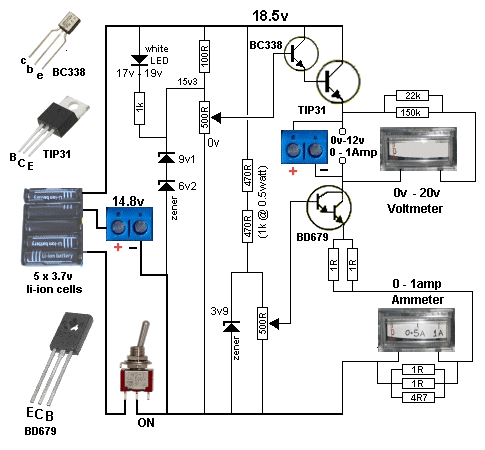
POWER SUPPLY MkII Circuit
You can use 2 x 470R @ 0.25watt or 1 x 1k @ 0.5watt


The new PC board uses 1k (in place of 220R shown above as the current limiting resistor for the white LED) to keep the brightness low to stop blinding you.
PARTS LIST Power Supply MkII
$20.00 plus $7.50 postage.
Click [HERE for details](mailto:colin@elechelp.com?Subject=Buying Power Supply MkII kit $20.00 plus $7.50 postage &Body=Please%20e-mail%20the%20cost%20of Buying Power Supply MkII kit $20.00 plus $7.50 postage by%20air%20mail%20to%20my%20country:**___****%20%20and%20send%20details%20of%20how%20I%20can%20pay%20for%20it.%20My%20name%20is:____)**
4 - 1R 0.25 watt resistors
1 - 4R7
1 - 100R
1 - 220R to be replaced with 1k (the old board shows 220R - new board uses 1k)
2 - 470R (or use 1k @ 0.5watt resistor)
1 - 1k (as shown in circuit above)
1 - 22k
1 - 150k
2 - 500R trim pots
2 - knobs to suit
1 - 3v9 zener
1 - 6v2 zener
1 - 9v zener
1 - BC338 transistor
1 - TIP31 transistor
1 - BD679 transistor
1 - 3mm white LED
4 - 2-screw terminal blocks
2 - heat fins
4 - sets of nuts and bolts and 5 washers
4 - hook-up wire for battery boxes (to replace the rubbish on the battery boxes)
2 - side-view panel meters and 2 stickers and foam tape to hold them in position
1 - toggle switch
10cm 0.5mm tinned copper wire for meters
30cm fine solder
Backing card and 4 feet and foam tape
1 - Power Supply MkII PC Board
Trickle Charger Components are included:
- 2 - 180R4 - 3v9 zeners
- 2 - 9v zeners
- 3 - 3mm white LEDs
- Trickle Charger PCB
Single-cell charger kit $7.00:
- 1 - USB voltage/current monitor module
- 1 - single cell charger PC board
- 1 - single cell battery box
- 1 - 1R0 5-watt wire wound resistor**
These parts are not included in the kit:
- 5 - 18650 Li-ion cells
- 1 - 4-cell battery box
- 1 - single cell battery holder
- 1 - 4 cell charger
- 1 - single cell charger or USB charger module and single cell battery box These items can be bought on eBay.
That’s all you need to know. You have the circuit diagram; a photo of the board and a parts list.
All the components for the board are in the kit and the extra’s are: 5 Li-ion cells, a 4-cell holder and a single cell holder, plus you will need a charger for the cells and these items can be purchased on eBay.
The rest of the article explains how to charge the cells and how to use the CURRENT LIMITING feature as well as a lot of handy information that will help you understand how this type of circuit works.
It is not simple to produce a variable power supply with adjustable current and that’s why there are few if any circuits on the web.
CURRENT LIMITING (current adjustable)
This feature is very handy when you are designing a project.
By limiting the current, you can connect a project and if the current is in excess of the setting, the voltage will reduce and nothing will be damaged. When the voltage reduces, the current also reduces and this is how you protect the circuit under test.
HOW TO USE THE CURRENT LIMITING FEATURE
This is something that has never been explained before.
To use the current limiting feature, the voltage is turned up a small amount and then the current limiting knob us turned a small amount so a small voltage will appear on the output. Now turn the voltage knob to the desired voltage.
Now connect the project to the output terminals and the voltage will possibly drop to near zero.
Now increase the current until the voltage rises to the desired voltage.
Read the current and this will let you know the current taken by the project.
While increasing the current you should monitor the ammeter and if it is higher than expected, you may have a fault in the project.
CURRENT TAKEN BY A PROJECT
The current taken by a project (the project you connect to this Power Supply) can be determined by following the steps described above.
Suppose your project requires 5v and takes 350mA.
Turn the current limiting knob slightly and then turn the voltage knob until the voltmeter reads 5v.
Connect the project. The voltage will drop to zero.
Now increase the current capability of the power supply by turning the current-limit knob and as soon as the voltmeter reads 5v, the current taken by the project can be determined.
If you increase the current-limit knob, the current will not increase because the Power Supply has indicated the project takes 350mA.
All you are doing is increasing the capability of the power supply to deliver more current, but the project does not want any more current and it is the deciding factor.
If the project is a 5v amplifier and takes between 100mA and 430mA, you will need to increase the current to a maximum of 430mA to allow for the peaks in current. If you only adjust for 300mA, the voltage will drop during the times when more than 300mA is requested. The amplifier will not get any more than 300mA and when a higher current would normally flow, the voltage will not drop to say 4v and the current will not pass 300mA. The result will be some form of distortion in the output of the audio amplifier.
THE 18650 Li-ion CELLS
We have used five 18650 Li-ion cells for this power supply.
These cells are very cheap on eBay and come in all sorts of capacity. Some start at 2400mA-hr and others are 12,000mA-hr.
Realistically, you can only allow about 2Amp-Hr and even though some will take many hours to charge, they will fail in a few minutes when being used.
This is a faulty cell and you will have to throw it out.
The cells shown in the photo say 6000mAh. They were tested and had an actual capacity of 2,000mA-hr. You cannot believe anything you see on a battery or cell. It might be true and it might be HYPE.
If the voltage drops from 19v to about 16v, one of the cells has failed and it will be quite warm. That’s how you can quickly identify a fault cell. Buy a few extra cells to replace the faulty ones.
Four cells are held in a 4-cell battery box and one cell in a single cell holder.
This allows us to provide a 12v (actually 14.8v) output with 5 amp or more current as a direct output from the auxiliary terminals and 12v with current limit from the front terminals.
The battery leads, switch and trackwork will “go up in smoke” if a current higher 10 amps is taken from the 12v - 14v terminals.
CHARGING THE 18650 Li-ion CELLS
Four of the Li-ion cells used in this project can be charged at the same time in a 4-cell charger, shown in the following picture:

It charges each cell separately and monitors each cell. The cost of these chargers is very small (less than $5.00 on eBay), but they only charge each cell at about 100mA. For a 2-Amp-hr cell, this will take 24 hours.
The fifth cell can be charged with a single-cell charger:


A single cell charger will look something like the images above. It will plug into the wall-socket and charge at about 70mA. These cost less than $2.00 on eBay.
You can also get a 2-cell charger:

No information is provided for these chargers. We do not know if the charger will charge the cells individually. If one cell is charged, does the charger continue to charge the other cell? What is the charge rate? It will be about 70mA to 100mA but this could be 35mA to 50mA per cell.
Do not buy one of these 4-cell charger modules:

These modules require an input voltage of 18v and a current up to 4 amps or more.
You will need a 100VA transformer and circuitry to cater for this module. This is outside the scope of this article.
For a fast charge, you can get a module that connects to your USB port will charge at up to 1 amp and you will need to wire it to a single cell holder.
There are two versions: mini and micro socket - about $1.00 on eBay.


See below for connection to USB socket on a laptop

Here is a different charging module but the hook-up is the same.
If you want to charge the cells quickly, you will have to charge them one-at-a-time via the USB port of your computer.
This port will only deliver 1 amp and the PCB shown above will take up to 1 amp during the initial charging of the cell.
The single cell battery box costs about $2.00 on eBay.
If you are going to use the project for long periods of time, you will need to buy 2 sets of cells.
You cannot put an ammeter in-line with the Li-ion cell because the slight voltage-drop across the ammeter will upset the charging. The charger will think the cells has an extra 0.3v across it and turn OFF !!
The only way to detect the charging-current is to monitor the current entering the charger.
The following image shows Li-ion charger board connected to an adapter.
This is the Single-cell charger kit $7.00:
- 1 - USB voltage/current monitor module
- 1 - single cell charger PC board
- 1 - single cell battery box
- 1 - 1R0 5-watt wire wound resistor


5.07v

0.23Amps
The adapter is connected to a USB monitor module that shows the voltage and current. It alternated the display automatically every 4 seconds
The current starts at about 230mA and drops slightly as the cell becomes charged.
Two LEDs on the charger board show RED for “charging” and GREEN for “charged.”
The single and double-cell charger supplies about 70mA. The charger board supplies about 230mA (about 3 times).
The 1R0 5watt resistor is designed to discharge a cell safely to a minimum voltage of 2.8v.
You need to place a voltmeter across the resistor while discharging to make sure you do not discharge the cell below its recommended minimum.
The USB voltage-current module and the adapter and Li-ion charger board and 1 cell holder and 1R0 5 watt resistor is available from Talking Electronics for $7.00 plus postage.
TRICKLE CHARGING
You cannot trickle charge Li-ion cells because they cannot absorb overcharge. When fully charged, the charge current must be cut off. A continuous trickle charge would cause plating of metallic lithium and damage the cell.
However the TRICKLE CHARGE circuit we have developed is zener regulated and will not rise above 20.5v for a 5-cell charger.
This allows 4.1v for each cell and corresponds to 80% charge. We are assuming each cell will charge at the same rate and produce the same terminal voltage but the charge-current we are providing is so low that that nothing will overheat or explode.
The Trickle Charger circuit is designed to be left connected all the time and will deliver about 500mA-hr to the cells per day, providing the cells are at a state of discharge.
If they are 70% charged, they will only get an extra 10%.
The circuit is very simple and uses 2 x 12v AC to DC adaptors or a single 24v adapter. If you supply more than 24v, the 180R current-limiting resistors will have to be increased.
The circuit will not work with a voltage below 22v.
If the voltage across the 5 cells is 20v, the cells are 75% charged.
If the voltage across the 5 cells is 19v5, the cells are 70% charged.
The charged discussed above will charge the cell to about 95% but if you are using the project for general-purpose work, the Trickle Charger will be suitable.
The double-sets of diodes are needed to dissipate the heat. They dissipate the current from the charger when the cells are charged.
The circuit is designed to deliver a maximum of 50mA and about 35mA goes to the cells when charging and then the 50mA is passed to the zeners and LEDs when they are charged. Each LED passes about 15mA, the maximum for a 3mm LED.
When zeners are in a circuit and current is passing through them, the actual voltage appearing across the zener is higher than the value printed on it. That’s why we have 9v1 and two 3v9 and white LEDs to produce a terminal voltage of 21v3. It all depends on the current flowing through the zener and the zener-voltage. About 0.8v is dropped across the signal diode, leaving about 20.5 for charging the cells. All these voltages are heavily dependent on the manufacturer of the component and the wattage (dissipation) of the component. That’s why we have provided very large lands and tracks on the PC board, to reduce the temperature-rise of each component.
The tiny zeners are really only about 250mW dissipation, but some manufacturers allow 400mW and other allow 500mW. We have allowed 250mW and that’s why we have doubled-up the zener strings.
If you are going to use our own zener diodes, you will need to build the circuit and accurately measure the output voltage with a digital meter before connecting the Li-ion cells. The output voltage BEFORE THE CHARGER IS CONNECTED, should be 20v5 to 20v7. This will prevent the battery being charged above 80%. You cannot measure the output when the battery is connected as the battery pulls the output voltage down during the charging process.
80% to 90% CHARGED (5 CELLS) = 20.6v to 20.7v
Once you connect the Trickle Charger, you should read the voltage across the battery after 12 hours of charging. The prototype measured 20.6v and did not rise above this value after 2 days. This proves the circuit is working and not allowing the battery to charge above 20.6v
You cannot measure the current entering the battery as the leads of the multimeter will have a resistance within the meter and the charging circuit will think the battery is 0.2v higher than it actually is. (You will have to study what I have said … to understand it).
This will reduce the charging current considerably and give a false reading.
A battery charged to 80% will still give a short-circuit current of at least 50 amps (that is the full capability of the battery) and you are dealing with a very dangerous item. A short circuit can create a burnt component and even a fire, so don’t have any paper or cloth anywhere near the Power Supply when you are not in attendance.
Even a battery at 10% can deliver a high current and melt all the tracks on the PC board. In fact the tracks are an effective “fuse” and will “go up in smoke” when a high current flows.
Two wires touched on our prototype and melted the battery box. The smell filled the house.
That’s why we produced a printed circuit aboard and made everything neat and compact and safe.
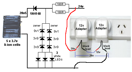
TRICKLE CHARGER CIRCUIT
The Trickle Charger components and PCB are included in the kit. You need 2 x 12v adapters or a 24v adapter and you can leave the Trickle Charger connected and not have to worry about the cells.
The 5 cells remain connected to the project ALL THE TIME and you can use it every day as the charger will charge the cells over-night.
The Trickle Charger will only work with an input voltage of 22v to 24v.
This gives between 1v and 3v “Headroom.” If the voltage is below 22v, the battery will receive NO CHARGE. If the voltage is above 24v, the 180R resistors will get too hot.
FREE CELLS
The 5 18650 Li-Ion cells can be obtained from old Lap Top batteries. There are 6 cells in most laptops and generally only 1 or 2 are not able to be charged. When you take the cover off the cells (by cutting or using a soldering iron to melt a rectangle on the cover of the cells) you will be able to remove them with the charging board.
You will not need the charging board as it is specially designed for the Lap Top.
The good cells will read 4.01v and the faulty cells will read 3.5v. It does not matter if you cannot determine the fault cells as you will locate them later.
Here is a photo of the 6 cells and charging board:

Separate the cells and keep as much of the tags as possible.

For this project you will need 5 cells. Start by taping 2 cells together with the positive of one and the negative of the other at one end. Solder the tabs together.
Now put two cells on top of these with the negative of a top-cell above the positive of the lower cell. Solder the bottom cell to the top cell. Do the same with the other.
Now take a reading from the output of the 4 cells. It should be very close to 12.8v.

Now add the 5th cell to the top and tape them all together so they do not move.
Connect a green wire to the negative terminal, a yellow wire to the 12.8v terminal and a red wire to the 17v (the top positive terminal). See the battery box above (connected to the project) for assistance.
Now get a single-cell charger board and solder the leads from a 5v plug pack to the ”+” and ”-” terminals on the board. Solder the female plug to the output of the charger board and make five pin-adapters and solder them to each cell of the battery pack.
Identify the positive connection.
You will now be able to charge each cell individually with a 1-amp charger board. It has a red LED to show charging and a blue LED to indicate the cell is charged.
Make sure the pins all have the positive on the positive on the left-side so the charger-board can be easily plugged-in.
It will take up to 2 to 3 hours to fully charge each cell and the terminal voltage will be 4.2v
Make sure the charger is 1 amp or higher as some 1 amp chargers drop to 4.5v when charging and the cell takes a long time to charge.
You can build another charger-board and charge 2 cells at the same time with two separate plug-packs because the plug-packs provide isolation.
HIGH CURRENT
Having and using a high current power supply is a very dangerous thing.
Just one cell can deliver a high current and completely melt the battery box.
This has just happened on the workbench and smoke filled the room. The two leads of the 3.7v cell touched each other and the cell is now too hot to touch and the end of the battery box has melted onto the bench.
So, it can happen at any time.
That’s why you have to be careful and not have any flying leads touching each other when you are experimenting.
The battery boxes use very thin leads and the ends are poorly terminated. They fall off very easily. The first thing you will have to do is replace the thin leads with thicker leads. These are supplied in the kit and are soldered to the eyelets on the boxes.
Then tape the single box the side of the 4-cell holder to make a 5-cell battery box.
Connect the 4 leads to the screw terminals provided on the PC board.
Fit the cells ONLY after all the components have been fitted to the board and the switch is OFF.
TESTING THE PROJECT
Remove the negative wire from the single-cell holder and fit a 12v car globe between the terminal and negative lead. The car globe needs to be a low wattage type. Alternatively use one strand of the hook-up wire and push it into the screw terminals. It will act as a low current fuse.
Click the power switch ON and OFF very quickly.
The globe should not illuminate and the thin wire should not “fuse.”
Turn the VOLTAGE and CURRENT knobs fully clockwise and click the power switch ON and OFF very quickly.
Do a few more test a bit slower and the globe should never illuminate.
Now remove the globe (or wire) and re-fit the negative lead.
Try the ON / OFF switch again and make sure nothing gets hot or starts to smoke.
You have now half-tested the project and confirmed that nothing is shorting or fitted incorrectly. It’s only a preliminary test, but it half-checks everything.
You have to be very careful when you have a high-current available.
Now check the output of the power supply.
Fit a car globe to the output.
Some car globes have a low-wattage filament and a high-wattage filament.
Use the low-wattage.
If you are buying a globe, look for 6 watts to 12 watts. Do not use over 12 watt globe.
The power supply will not deliver over 1 amp.
It is designed to work up to 1 amp and if the globe starts to take more than 1 amp, (as you turn up the voltage), the voltage will stop at about 8 to 9 volts and the globe will not get very bright.
14 volt OUTPUT
The project has a separate output called an AUXILIARY OUTPUT that connects directly to 4 cells and delivers a voltage of about 14v.
There is no current-limiting on this output and if the terminals are shorted, a very high current will flow.
The PC board has thick tracks to this output but they will only allow 10 amps to flow and a current in excess of 15 amps will blow the tracks off the board.
If you need 15 amps, you will have to add 0.5mm tinned copper wire under the board between the battery terminals and the 14v output.
HOW THE CIRCUIT WORKS
The circuit is basically an adjustable power supply with the voltage being adjusted from 0v to 12v via a pot and the current adjustable from zero to 1 amp.
The only problem with these two features is the need for an input voltage about 4v higher than the output.
The voltage-adjust section of the circuit needs about 2v across the transistor providing the voltage.
This is only noticed when the output voltage is turned to maximum and then the drop across the transistor is realised.
The other drop occurs across the current-limiting section and when the current is a maximum, this drop is only about 2.6 volts with an ideal circuit.
But since we have about 5 to 7 voltage available, we have changed some of the components in the current-limiting section.
THE SUPPLY
The cheapest way to get a 12v DC supply is with 18650 Li-Ion cells. These are rated at 3.7v and the makers claim a capacity from 4900mA-Hr to 6,000mA-Hr.
These cells were tested and found to deliver about 1,000mA-Hr to 2,000mA-Hr, which is way below the stated capacity, but for $2.00, who’s complaining?
At $2.00 per cell, they provide the cheapest “high-current” battery on the market. For short-term requirements, they can deliver 20 to 30 amp, so you are dealing with a supply that can easily burn-out any normal wiring. So, you have to be careful not to produce a short-circuit.”
You can get single cell holders and multi-cell holders and also single cell chargers for $2.00, so it’s very easy to produce a “battery” - a number of cells in series and easy to charge them.
The simplest and cheapest way to use these cells to produce a BATTERY is to put 4 in series to get 14.8v
You can put them in single-cell holders or a 4-cell holder.
Charging this type of cell is fairly technical and they should not be over-charged (in other words, the charging current should be reduced or removed when the battery is fully charged) or discharged below 2.5v.
But how do you know when the battery is charged?
You can buy single cell chargers for $2.50 and they have a built-in charging circuit that detects a peak voltage that the cell rises-to when it is fully charged.
If you buy 1, 2 or 4 chargers for $2.00 each and take the cells out of the “battery box” and charge them individually, you will be able to charge them overnight.
The cheap chargers provide a charge current of 80mA to 100mA and it will take 24 hours to charge the 2A-hr cell.
There is one more way to use the Li-ion cells.
You can create a 14.8v battery and connect it up to the project.
From the 15v AC of your train transformer, add a 1N4004 power diode and 2 x 47R resistors in series to the positive of the battery. These components will deliver about 100mA to the battery and allow you to use the battery for a longer period of time. Remove the charging when you are not running the trains.
When the cells get to 10v, you will have to put them on the charger.
Work out how much extra time this produced and you may be able to put the two 47R resistors in parallel to increase the time.
But the charging must be removed after running the trains as it will not stop charging the cells and they will be over-charged.
Finally, another way to get a high current is to combine two power supplies.
Two power supplies can be connected with the two positive leads together and the two negative leads together.
If they produce exactly the same voltage, the output current will be addition of each supply.
If the voltages are not equal, the supply with the higher voltage will deliver more current.
The only way o determine the success of this arrangement is to use each supply separately and measure the drop in voltage as the current is increased.
Possibly the only way to measure this is to use the THROTTLE and measure the voltage at full throttle.
Now combine the two power supplies and see the improvement.
CONSTRUCTION
Assembly of the PC board is straightforward.
All the components are clearly marked on the board and it is best to start with the resistors, then the zeners, transistors, followed by the pots and 2-screw terminal blocks.
The LED should be soldered so that it is 5mm above the board so the soldering does not overheat the LED and damage it. Solder only one lead at a time and very quickly. The LED is very easily damaged.
Make sure you identify the 3v9 as the wrong value will prevent the Power Supply operating correctly.
The TIP31 is soldered so the numbering on the chip can be seen BUT the BD 679 is soldered with the metal side of the transistor UP and you cannot see the numbers on the transistor.
The toggle switch is the last to be fitted. It gets soldered “either way around.”
The two knobs get pushed onto the shafts but first make sure the pot is fully anti-clockwise and then fit the knob a small amount and turn the pot so that the pointer moves around from about 7 O’clock to 5 O’clock. Now push the knob onto the shaft.
If this is not done correctly DO NOT twist the knob into position as you will
THE SCALES
The two panel meters are actually 0-1mA MOVEMENTS. This is the technical name for a coil and pointer BEFORE resistors are added in series or parallel, to turn the movement into a PANEL METER.
To create your own scale, the clear plastic front is removed by removing the sticky tape.
The scale is slid out of its grooves and reversed. Push the scale up against a curved rod of about 30mm diameter and replace it with the blank side showing. You can fit a white sticker to the scale and add the required numbers.
The voltmeter has series resistors to allow the pointer to read 0v to 12v and the ammeter has resistors to all the pointer to read 0 to 1Amp.
MOUNTING THE HEAT-FINS
The two transistors need to be soldered in place and all the other components should be fitted to the board before attaching the two heat-fins..
Start with the left heat-fin. The transistor will be soldered with TIP31 showing.
Use a short bolt M3x10mm and push it from underside. Fit 2 washers between the fin and the PC board. Add the heat-fin and screw on a nut. The other bolt fits up through the hole and through the TIP transistor. Tighten both slightly and the heat-fin will be parallel to the board.
The second heat-fin uses the longer 16mm bolts and the writing on the BD transistor cannot be seen as it is against the PC board. Use 3 washers on the 4th bolt to make the heat-fin sit parallel to the PC board. Don’t over-tighten anything.
When the project is complete and tested, the underside of the board is fitted with small pieces of double-sided foam tape (supplied in the kit) and then the thick card is used to cover the board.
4 rubber feet are then added to the corners and the project is complete.
This will prevent wires etc on your workbench touching the underside of the project and creating a short circuit.
The lamp shown in the photo is 5watt but a 12v 15watt car globe has also been used for testing the supply and nothing gets hot. The voltage to the 15 watt globe does not rise above 10v as this is where the globe takes 1amp and that is the limitation of the power supply.
You can fit the cells under the project or sit the project on the work bench. The 4 feet and card on the back of the PC board will prevent any short-circuits.
You now have a $40.00 Power Supply that is equal to a $100 supply. And you built it yourself.
EXPANDED VOLTMETER
Here’s a handy addition you can fit to this project, or any type of battery.

It is a voltmeter that shows full voltage for the battery are monitoring and as the voltage falls 3v, the needle (pointer) moves across the SCALE to ZERO.
It’s a bit like the x5 expansion you get in photography.
In our case, the full scale represents 20.8v and the zero-mark represents about 17v.
The secret is the zener diode (or string of zener diodes) that “absorb” the first 17v and this voltage does not show on the meter.
It is only the voltage above 17v, that moves the pointer.
So, how do you create an EXPANDED VOLTAGE SCALE.
The mathematics is quite complex. But we will do it without any maths.
You can get any meter (called a MOVEMENT). A Movement does not have any resistors connected to the terminals.
These resistors may be inside the case and this will be especially true if the movement is marked “0-100mA” or “0-10v” or “0-1amp”
You do not need to know the SENSITIVITY of the movement as we will be converting it by EXPERIMENTATION.
If you do know the sensitivity, it might be 30uA FSD. This means it takes one-third of a milliamp to swing the needle full-scale.
To get you some-where in the picture, this means a 30k resistor in series with one of the terminals will produce full scale deflection when 1v is applied.
If the movement is 100uA, it will need 10k. If the movement is 1mA, it will need 1k.
The first thing to do is to connect a number of zener diodes together to get the “ZENER VOLTAGE.” This is the minimum voltage you want to detect.
A zener diode will not drop the exact voltage shown on its body AND the drop will increase slightly as the voltage of the power supply increases.
That’s why this project is not reliable by about 300mV.
But it’s the principle that we want to show.
Now, add a 10k resistor to the zener string and connect the movement to the battery via a switch.
For the first measurement we need the battery to be fully charged.
Turn the project ON and look at the pointer. Increase or decrease the value of the resistor until the pointer is at FULL SCALE.
Now connect a heavy load to the battery and watch the pointer drop towards zero.
When it is near zero, read the voltage of the power supply.
This is the principle behind an EXPANDED SCALE METER.
You can set the zener voltage to a lower value or a higher value and the meter will let you know when this percentage of energy has been removed from the battery.

Quick Links
Legal Stuff
Social Media