Table Of Contents
To-Fro Module (built) $35.00USD plus post $6.50USD
To buy: [To-Fro Module](mailto:colin@elechelp.com?Subject=Buying To-FRO Module for $35.00USD plus $6.50USD postage &Body=Please e-mail the cost of To-FRO Module by air mail to my country:****___**** and send details of how I can pay for it. My name is:____)
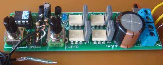
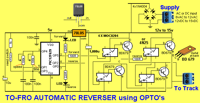
This module uses two opto-couplers to turn ON the two left-side transistors to make the loco travel forwards of the two right-side transistors for reverse. It is an AUTOMATIC REVERSER and will accept AC or DC input from 12v to 15v DC or up to 12v AC (this becomes 17v DC via the module).
It also has a THROTTLE CONTROL to produce very slow travel via PWM with increments from just about zero to nearly full speed. The PWM ensures the loco will start at a very low setting.
The reed switch is designed to provide REGISTRATION. In other words it sets the train for the same number of seconds and (hopefully) the same distance on each cycle.
To make sure this happens, the loco is “inched” backwards towards the reed switch and it then moves forwards, to re-start the cycle.
SIMPLE SET-UP
You only need an isolated section of track. Simply connect the two alligator clips to the rails around either way.
Fit the magnet under the loco at a position that will activate the reed switch.
Set the speed to the lowest value and the time to the shortest number of seconds (and then increase the time to get higher than zero time). Increase both values to suit the length of track you are using. This will allow the train to constantly shuttle from one end to the other.
Ideally you can use a small track-maintenance vehicle for this. Make sure the track is clean as a light maintenance vehicle will not make very good contact with the rails if any oxidation is present.
Turn the module ON and the train will move slowly towards the reed switch (maybe backwards) in short bursts until the reed switch is reached. The loco will stop and move in the other direction and then the electronics in the module will detect the speed and time you have set on the two pots.
The speed of the train will depend on the setting of the SPEED pot and it will continue to move for the number of seconds as determined by the TIME setting.
The train will then stop at the other end of the track and reverse at the same speed and for the same number of seconds back to the starting position.
It will then “inch” towards the reed switch and start the cycle again.
It will take a few adjustments to get the speed and time adjusted correctly for the length of track you are using. And then it will repeat the action, again and again.
4 APPLICATIONS
The project is designed for a number of different applications:
- It can be used to test a length of track without having to constantly be at the controller. You can move freely around the layout and view the train from different angles.
- It can be used to produce movement in the background (such as a second train) without having to attend to the train. This is called “attract mode.”
- It can be set-up for children to use the layout without having to monitor their use of the controls.
- It can be used show the layout in an exhibition in the “attract mode.”
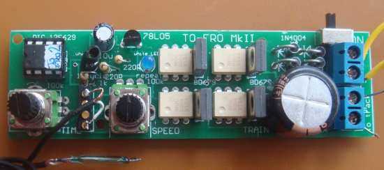
The reed switch is now included with the module.
The TIME pot and the SPEED is set (and adjusted) so
the train reaches the end of the track - then stops - then
returns to the starting position.
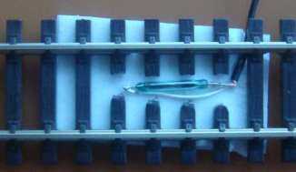
The reed switch is fitted along the length of the track
because the centre of the reed switch is not sensitive.
Allow 15cm of track past the reed switch to prevent
the train running out of track.
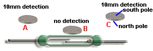
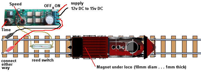
The loco reverses back to the reed switch so that each excursion is
the same distance down the track. It is called REGISTRATION.
The voltage and current to the loco is pulsed and this means the transistors are turned on for a short period and turned off for a short period.
The transistors will not get warm and the pulses to the motor will will allow the loco to start very slowly.
The voltage across the transistors and the bridge will be about 6v and this means about 6v will be lost from the supply. If the supply is 12v, the motor will see about 6v and you will not be able to get full throttle.
But this project is not designed for speed. It is designed for “effect” and to get the most out of a short length of track.
If you have a long or heavy train, you can increase the supply as it will not damage the loco.
The module comes fully built and tested for $35.00 as we build them 10 at a time and test them with a 300mA motor and 12v DC supply to make sure everything works. You can buy a kit for $25.00 and if you want a kit, you will need to email Colin Mitchell: colin@elechelp.com for all the details. The kit comes with a reed switch and magnet and 1200mm of twin wire and two alligator clips and wire, so everything is ready TO GO.
TEST EQUIPMENT
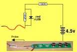
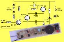
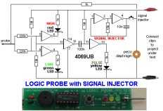
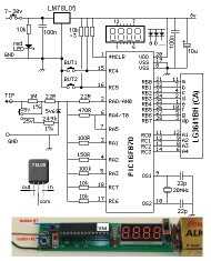
Talking Electronics has a number of pieces of TEST EQUIPMENT to help in the design and testing of projects.
Of course you can use a multimeter for most of the testing but some of the “tricky” faults need a special piece of equipment.
You may only need a LOGIC PROBE once a month, but the project you are designing will come to a stand-still if you can’t locate a problem.
We designed all these projects because we needed them ourselves.
Add one of them to each order you place with Talking Electronics and eventually you will have the whole range.
Related Posts
Quick Links
Legal Stuff
Social Media


