Table Of Contents
Cost: $7.00 including postage
[Kits are available](mailto:colin@elechelp.com?Subject=Buying PIC Burner Board kit&Body=Please e-mail the cost of PIC Burner Board kit by air mail to my country:****___**** and send details of how I can pay for it. My name is:____)
This project allows you to burn chips with PIC-2 Programmer or any other PIC programmer
This project is very simple.
It plugs into the PIC-2 (PIC-3) Programmer so you can “burn” 8-pin and 18-pin chips.
You are actually “programming” them, but the word “Programming” has already been used to describe the skill of writing a PROGRAM.
I am surprised no-one has come up with a simple way to create a programmed chip with the PIC-2 Programmer.
But we have.
It plugs into the end of the Programmer and has an 18 pin pin socket that also takes 8-pin chips.
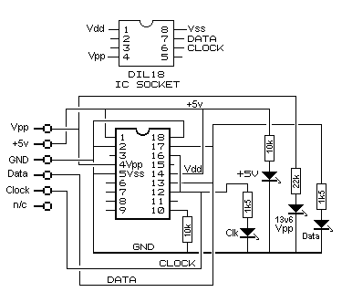
PIC BURNER BOARD CIRCUIT
It also has 4 LEDs to show: POWER (5v), PROGRAMMING VOLTAGE (Vpp), CLOCK and DATA as the chip is accessed by the programmer.
In some cases the chip will start to “run” after it is programmed and blink some of the LEDs.
This is the case with many of the projects we have produced and shows the chip has been programmed. This will only occur with some programmers because it keeps 5v on the chip after it is programmed. The PICkit 2 removes the voltage and nothing can be viewed.
We have used a standard 18 pin IC socket and you don’t need a zif socket.
By simply plugging the PIC chip into another socket (or 2 sockets) you can easily handle the chip and plug it into the project you are developing and transfer it to this board for programming.
By slightly oiling the pins with your fingers, it will be easy to remove the chip and socket from the board as the pins will no-longer have any “grip.”
The LEDs are high-bright and glow with a fraction of a milliamp.
They pose a very high impedance to the signals and have no effect on the programming.
It’s handy to see what’s happening, especially when you are having trouble programming a chip.
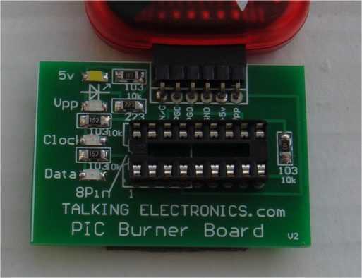
The SM resistor for the Clock LED and Data LED is 1k5 to produce more brightness from the LEDs.
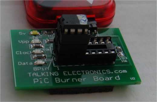
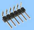
Fit the 90° header slightly above the board so the PICkit-2 programmer will fit into the pins. Soft rubber feet are also included in the kit.
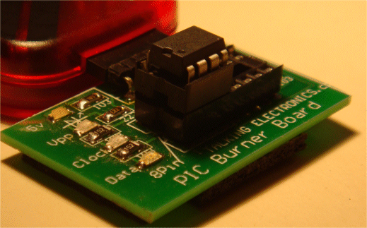
Always fit the PIC chip into an 8-pin IC socket to make it easy to transport the chips from the burner to the project. You can carry the PIC chip in two 8-pin sockets if you find the single socket too difficult to move. The kit contains 3 pieces of soft rubber to be cut as feet for the board. You will also need double-sided sticky-tape to attach the feet to the underside of the board.
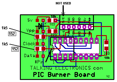
If you are using a burner with 5 pins, the first pin is NOT USED. If you are using PICkit-2, the first pin is not connected to anything. The 6 pins fit directly into the PICkit-2 socket.
PIC Burner Board Parts List
Cost:$7.00 including postage
[Kits are available](mailto:colin@elechelp.com?Subject=Buying PIC Burner Board kit&Body=Please e-mail the cost of PIC Burner Board kit by air mail to my country:****___**** and send details of how I can pay for it. My name is:____)
- 2 - 10k surface mount resistors (the PC board shows 4 x 10k, but use 2 x 10k and 2 x 1k5)
- 2 - 1k5 surface mount resistors
- 1 - 22k surface mount resistor
- 4 - coloured surface mount LEDs
- 1 - 18 pin IC socket
- 1 - 6-pin 90° header
- 1 - 10cm fine solder
- 1 - soft rubber for feet
- 1 - double sided tape
- 1 - PIC Burner PCB
PROGRAM 8-PIN SURFACE MOUNT CHIPS !!
This adaptor socket is called: Wide SOIC8 to DIP8 Programmer Adapter IC Test Socket Converter Module 200MIL (i.e.: the bottom pins are 0.2inches wide)
You can also buy the same socket with the 8 bottom pins at a spacing of 0.15inches.
It does not matter which socket you buy as they can adjusted and soldered to the 8-pin component header pins supplied when you buy the PIC Burner Board.
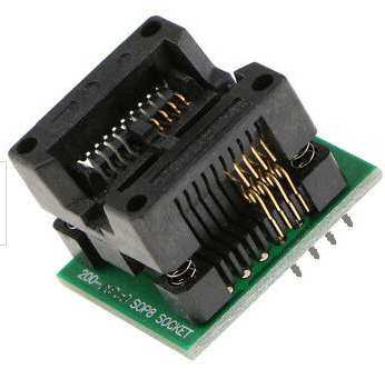
You can buy an adapter socket to program surface-mount 8-pin micros for less than $5.00 on eBay.
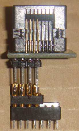
The pins on the bottom of the socket are too wide for the socket on the PIC Burner Board and you need to get a 14 pin or 18 pin socket and two rows of 4-pin component-carrier pins. The following photo shows the adapter soldered to the pins and the pins pushed into a 14 pin IC socket to create stability. Ask for the socket and component-header pins when ordering the PIC Burner Board from Talking Electronics.
Simply push any part of the top of the Adapter socket and the 8 “claws” will open up to load the surface-mount chip onto the programming pins. Release the top and the claws will hold the chip in place. This is a fairly fiddly operation and you may need tweezers to place the chip in position. Pin 1 is on the left-end of the socket in the image below. And pin 1 of the 14-pin or 18-pin socket that holds the adapter is also on the left of the photo.
If your program contains a routine to say flash a LED, the PIC Burner Board will power the surface-mount chip (or through-hole chip) as soon as it is programmed, and you may be lucky to see the LEDs on the board flashing to prove the chip is working, before you remove it.
Quick Links
Legal Stuff
Social Media


