

To buy a $4.50 kit: [Key Hole Light Kit](mailto:colin@elechelp.com?Subject=Buying Key Hole Light kit&Body=Please e-mail the cost of sending $4.50 Key Hole Light Kit by air mail to my country:****___**** and send details of how I can pay for it. My name is:****___****)
Necessity is the Mother of Invention.
The best ideas come from a personal need.
The front door at the authors house is dark at night-time and it is difficult to find the key-hole.
This project solves the problem by shining a light on the problem when the button is pressed.
The circuit illuminates a LED for about 10 seconds so you can fit the key.
The circuit gradually dies and consumes absolutely no current when not being used.
Although one cell will illuminate a white LED when it is new, this is not reliable so we use 2 coin-cells and a constant-current circuit so the LED maintains the same brightness over the full life of the cells.
The current is less than 10mA and the LED we supply on the kit has very good brightness at this current.
THE CIRCUIT
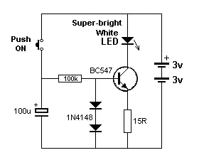
KEY-HOLE LIGHT CIRCUIT
The circuit is very clever. 6 components do TWO things. They create a time-delay and provide a constant-current for the LED.
The time delay consists of the 100u and 100k resistor. The constant current consists of the two diodes and 15R resistor. The transistor is the amplifying device.
When the button is pressed, the 100u is instantly fully charged and this puts a voltage (and current) on the base of the transistor. The maximum current will be 50uA and the gain of the transistor will increase this 200 to 400 times to produce a maximum of 50 x 200 = 10mA to 20mA collector current. This is sufficient for our application.
The transistor turns ON when the electro is charged and current flows through the 15R resistor. At the moment we do not know how much current flows through the 15R resistor, but there are two facts we know about the section of the circuit we are analysing.
- The voltage on the base cannot rise above 0.7v + 0.7v due to the two diodes, and
- The voltage across the base-emitter junction is 0.7v when the transistor is turned ON.
This leaves exactly 0.7v for the voltage across the 15R resistor and as the current increases, the voltage across the 15R resistor increases to 0.7v.
If the current increases further, the voltage across the 15R would increase to 0.8v and only 0.6v would be available for the base-emitter junction. This means the transistor would be turned off and this is NOT POSSIBLE. Thus the emitter voltage NEVER rises above 0.7v.
That’s why we call this a CONSTANT-CURRENT circuit.
The current passing through the emitter resistor is the same current passing through the collector-emitter terminals of the transistor and also through the LED.
It can be found from the following: V= IR.
0.7 = I x 15 I = 0.7/15 = 5mA
The actual voltage developed across the diodes and base-emitter junction is slightly different to 0.7v and the current was measured at 9mA.
This constant current will flow while the 100u has a voltage of about 6v and will decrease slightly as the electro discharges.
The circuit takes a very small current from the 100u to drive the base of the transistor and the electro gradually discharges.
When it reaches 1.4v, the circuit turns OFF completely and NO CURRENT is taken from the coin cells.
CONSTRUCTION
A kit of components is available from [Talking Electronics](mailto:colin@elechelp.com?Subject=Buying Key Hole Light kit&Body=Please e-mail the cost of sending $4.50 Key Hole Light Kit by air mail to my country:****___**** and send details of how I can pay for it. My name is:****___****) for $4.50
All the components are included in the kit and everything is identified on the board.


PARTS LIST
$4.50 plus $4.00 post
[Order a kit](mailto:colin@elechelp.com?subject=Buying Key Hole Light kit&Body=Please e-mail the cost of sending $4.50 Key Hole Light kit by air mail to my country: ****___**** and send details of how I can pay for it. My name is: “)
- 1 - 15R resistor
- 1 - 100k
- 1 - 100u electrolytic
- 2 - 1N4148 diodes
- 1 - BC547 transistor
- 1 - 5mm super-bright white LED
- 2 - coin cells - CR2016 (lithium cells)
- 1 - coin cell holder
- 1 - large tactile push button
- 10cm very fine solder
- 1 - Key Hole Light PCB
TEST EQUIPMENT
Talking Electronics has a number of pieces of TEST EQUIPMENT to help in the design and testing of projects.
Of course you can use a multimeter for most of the testing but some of the “tricky” faults need a special piece of equipment.
You may only need a LOGIC PROBE once a month, but the project you are designing will come to a stand-still if you can’t locate a problem.
We designed all these projects because we needed them ourselves.
Add one of them to each order you place with Talking Electronics and eventually you will have the whole range.


Quick Links
Legal Stuff
Social Media