Table Of Contents
To buy a kit: [Do it NOW](mailto:colin@elechelp.com?Subject=Buying Do It NOW kit&Body=Please e-mail the cost of sending Do It NOW Kit by air mail to my country:****___**** and send details of how I can pay for it. My name is:____)
$9.50 plus $4.50 post**
This project takes away all the complications of getting things done.
By simply pressing the TOUCH PAD you can be guided to avoid doing anything AT ALL.
It’s the most valuable piece of DECISION-MAKING equipment you will ever have.
INSTRUCTIONS
- Press the TOUCH PAD and wait for the LEDs to stop on a selection.
- If you don’t like the answer, try again !!!
- You must wait for the final LED to appear on the display and then go out, before removing your finger. The time-delay between the LED going out and removing your finger is when a random number is generated for the next LED.
- If you take your finger off the pad too soon, a new random number will not be generated.
THE CIRCUIT
This clever circuit does not need an ON/OFF switch.
It uses a TOUCH SENSOR to turn the project ON.
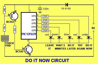
This is a good introduction to the concept of CURRENT GAIN, as this is the principle of how the TOUCH SENSOR works.
The TOUCH PAD is just like a RAIN ALARM PAD. When rain or moisture touches the pad, the alarm is activated.
You finger is just like a drop of rain. It contains moisture and some people have very dry skin while others have very moist skin.
The two sets of tracks are interleaved and spaced very close so that many of the tracks will be contacted by a light press of a finger.
Our tests showed a resistance of about 30k for a light press and here is how the resistance of your finger is transformed to a lower resistance to turn ON the circuit.
The gain of the surface-mount transistors we have used is 100 to 300 and in simple terms we can say the first transistor in the circuit is reducing the 30k by 100 to get 300 ohms.
The second transistor has the same effect and the final resistance is 3 ohms.
If this were the case, the voltage dropped across a 3 ohm resistor would be 60mV when the micro is driving a LED at 20mA.
In other words, the circuit would work perfectly as a loss of 60mV would not be noticed.
However the transistors really have a gain of about 300 and the effective resistance of the “turn-ON” circuit is less than one ohm.
You can see the effect of the turn-ON circuit by pressing very lightly on the pad and see the LEDs gradually increase in brightness.
You can also see the TOUCH SENSOR turns the chip ON fully as a slight amount of additional pressure creates full brightness.
When the finger is removed, both transistors turn OFF immediately and this is exactly like opening a switch.
This TOUCH SENSOR circuit achieves 3 results:
- It activates the circuit
- It saves an ON/OFF switch
- It prevents the circuit being left ON.
If you want to work out the effect of the TOUCH SENSOR circuit using “current” equations, the 30k in series with 10k will allow 11uA to flow in the base of the BC557 transistor. The transistor will increase this to 11 x 100 = 1.1mA via the collector.
The 2k2 resistor will not change this value. The gain of the BC547 will allow more than 100mA but the chip only requires 20mA. This means the two transistor DC amplifier will turn the project ON fully.
These calculations are only approximate because the gain of a BC547 and BC557 can be as high as 400 or as low as 70, depending on the collector current and the quality of the transistor. The BC557 is in a low-current situation and can exhibit a gain of 400 in this situation and the gain can drop to 70 when the collector current is 50mA or more.
It is absolutely pointless looking at any graphs to work out the overall gain of the circuit because you do not know the actual quality of each transistor. You may have a genuine transistor or a clone. It may even be a reject that is quite noisy. None of this matters in this simple circuit.
When the BC547 is not conducting, pin 8 of the micro and all the LEDs are not connected to the 0v rail and the circuit takes absolutely NO current.
For this reason, no ON/OFF switch is required.
The 2M2 is deigned to reduce the impedance of the base-emitter junction of the BC557 so no current flows through the collector circuit when the touch pad is not touched.
These transistors have a very high capability of detecting microscopic amounts of current-flow and amplifying the result. Any slight amount of dirt on the TOUCH PAD will be detected and create a “leakage,” so keep your finger clean.
The 2k2 limits the current into the base of the BC547, if the TOUCH PAD is accidentally shorted with a piece of metal.
The 1N4148 drops the 6v supply to 5.4v as this is the maximum for the PIC chip.
THE PROGRAM
The program sets up the in/out port as OUTPUTS.
Five simple delay sub-routines are needed to display the LEDs for between 20mS and 5 seconds.
The micro then goes to the Main section of the program where it produces a “running display” by turning on a LED and calling a delay. The LED is then turned off and the next LED is displayed.
This routine is set-up with a loop feature and it can be called any number of times, depending on the value given to the loop counter.
The next sub-routine does the same but has a shorter delay-value.
Finally, the next routine has a longer delay.
These routines give the effect of the LEDs speeding-up and slowing down.
The micro then goes to the Display sub-routine where it uses the value in the Random file to illuminate the final LED.
Lastly, the micro loops a small sub-routine that increments the Random file to a value of 4, waiting for the project to be closed down.
Fortunately, this value is held in the file when the project is turned off and is is used on the next activation.
This seems to work if the project is turned on again after a short period of time but the file is not guaranteed to hold this value when the power is removed.
RANDOM NUMBER
The display produces a “Running Effect” with slow-down and finishes on an unknown LED for 5 seconds.
To produce this effect requires a random number to be generated.
Random number generation is a very difficult thing to produce in a program. It requires a register to be incrementing at an unknown rate or to an unknown value.
In this project, the program creates a RANDOM NUMBER after the final LED has appeared on the display.
You must wait for the final LED to appear on the display AND GO OUT, before removing your finger. The time-delay between the LED going out and removing your finger is when a random number is generated for the next LED.
To create a RANDOM NUMBER, a file is incremented and when it is 4, the file is cleared and incremented again.
This will produce results between 0 and 3.
But the micro can be turned OFF at any time during this loop and during 5 of the 7 instructions, the file can be 4.
The file will remember this value during the short time when the micro is turned OFF and ON again.
GOING FURTHER
You can alter, change and improve the program in so many ways.
We have especially kept the program simple so you can say; “I can do better!”
The running display can have more steps between slow and fast and the random number routine can be designed to store the Random Number in EEPROM, rather than expecting the file to hold the value when power is removed.
The LEDs can be dimmed with PWM and you can introduce flashing.
You can also reduce the length of the code by using “nested loops” instead of the “linear programming” we have used.
FILES
Here are the files for the project:
CONSTRUCTION
A kit of components is available from [Talking Electronics](mailto:colin@elechelp.com?Subject=Buying Do It NOW kit&Body=Please e-mail the cost of sending Do It NOW Kit by air mail to my country:****___**** and send details of how I can pay for it. My name is:____).
All the components are included in the kit and everything is identified on the board.
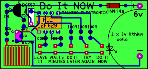
PARTS LIST
$9.50 plus $4.50 post
[Order a kit](mailto:colin@elechelp.com?Subject=Buying Do It NOW kit&Body=Please e-mail the cost of sending Do It NOW kit by air mail to my country:****___**** and send details of how I can pay for it. My name is:____)
4 - 220R resistors
1 - 2k2 resistor
1 - 10 resistor
1 - 2M2 resistor
2 - SM red LEDs
1 - SM green LED
1 - SM blue LED
1 - SM white LED
1 - 100n monoblock capacitor
1 - 1N4148 diode
1 - BC 547 transistor
1 - BC 557 transistor
1 - PIC12F629 (with Do It)
1 - 8 pin IC socket
2 - CR2024 coin cells
1 - coin cell holder
20cm very fine solder
1 - Do it NOW PCB
TEST EQUIPMENT
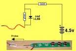
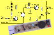
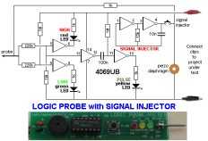
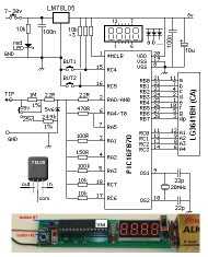
Talking Electronics has a number of pieces of TEST EQUIPMENT to help in the design and testing of projects.
Of course you can use a multimeter for most of the testing but some of the “tricky” faults need a special piece of equipment.
You may only need a LOGIC PROBE once a month, but the project you are designing will come to a stand-still if you can’t locate a problem.
We designed all these projects because we needed them ourselves.
Add one of them to each order you place with Talking Electronics and eventually you will have the whole range.
Quick Links
Legal Stuff
Social Media


