

Table Of Contents
SPOT
THE MISTAKES!
Page 32
One of the most-often criticized men in the world is the person who has changed just about everyone’s life.
It is the inventor of the software we all use everyday in our computer.
Maybe things have changed slightly in recent times but the originator who changed our computer from a blue screen with blocky writing, to a full-colour active screen, was BILL GATES with his MICROSOFT packages.
He has been criticized by lawyers, politicians, accountants, professors and engineers, but not one group has produced a better concept.
Agreed, there were some rival start-ups, but they all wanted $1,000 for a package when Microsoft was only $200.
Most inventors invent one item. Bill Gates invented one item and then went on to improve and expand it. That takes brilliance.
He could have sat back and counted the millions from the first release, but he went on to produce the next improvement and the next. Each stage was a huge advancement over the previous.
But the one thing no-one realises is this:
His programs required bigger and better and faster computers (operating systems) and he was forcing hardware manufacturers to come up with advancements that were 10 times better and faster and larger in storage capacity, all along the way.
My first computer had a 10 meg hard drive. The next was 80 meg and then it was hundreds of meg. Now we are taking about tera byte.
We went from 5.25 floppy disks to 3.5 and these only stored from 360kB to 1 meg of data. Programs came on 12 discs.
And then the internet was born.
Bill Gates finished up with so much money he now has full time staff dealing with humanitarian activities throughout the world.
Only an ignorant person would criticize him.
Only a person who has never done any programming.
And especially at a time 30 years ago when there was no hardware to run your programs and no-one to ask for advice or assistance.
It was like building on sand.

He only had speeds of 1MHz to 4MHz, a capacity of 64kB and a 10Meg hard drive.
And yet he released programs requiring an upgrade of 1,000% !!
That’s forward thinking in a time when IBM said the world would need 8 computers. He said he wanted to put a computer in everyone’s home.
That’s when they thought he was mad.
And he was wrong … every house has more than 3 computers!!!
The capacity of early computers was so small they could not run any of Bill Gate’s programs.
And when you think of it. All his programs were worthless. You had to buy another computer.
And 30 years ago, the term obsolescence, had not been coined. Everything lasted until the day it died.
He changed the world.
Not only did he introduce the word “updating,” but introduced the term: “buy a computer.”
And it was the introduction of “copies” and “clones” and “knockoffs” that brought computers to a cost below $1,000.
Yes, we have an enormous amount to thank him for. Maybe the world would have progressed to the same extent without him, but you can only say this if there were parallel inventors with the same forward thinking.
Yes. I know he took a lot of ideas from others and he was helped along the way.
I am only using his name as the “Front-Guy” and saying the whole revolution was brought about by a very small group of thinkers. And now this type of thinking has been imparted to millions of others. And that’s why we have an industry called the IT industry.
The biggest problem with University Graduates is this:
They “think and expect” their idea, project or circuit will work the first time.
They get lulled into a false concept of the “world of reality” by being involved in markings as high as 99.85%.
And when the circuit doesn’t work, they are LOST.
Although my circuits work 100% of the time. They all go through a series of steps and stages of improvement and adjustment until this result is achieved.
Even a microcontroller program will take 100 or more steps to get it finalised and sometimes a circuit board will take 3 or 4 changes and improvements to get to the final design.
Most of the time these changes are improvements or even total re-design with fewer, cheaper components.
But, in the end, the result is a robust, reliable project that anyone can build and get it to work as soon as it is turned ON.
As I have said for the past 50 years, it does not matter if the project does not work the first time. This is when and where you will start to learn electronics.
It’s only after diagnosing, testing and fixing a fault, that you will really learn electronics.
Anyone can build electronics projects and, in fact, out first 6 transistor superhetrodyne radios were build by 14 year-old children on the floor of their apartments in Hong Kong and sold in Australia for $2.50. But if the radio did not work, it would take a capable person to locate the problem.
The same applies today.
Products are made by the millions by either robots and unskilled workers, but the eventual success lies in the technical department to sort out any faults and get it to a stage of being produced with 100% reliability.
So, there is still a need for the “thinker.”
And that’s what we are providing.
The tools and knowledge to get you into the world of designing and producing products that will assist and advance the world in general.
And the best place to look is the area of aids for the sick and disabled.
This field is enormous and it just takes a little time to associate yourself with those-in- need to see what devices can be invented.
I will leave the rest to you.
Universities are constantly emailing me in the hope I would recommend one or more of their courses.
https://floridapoly.edu/degree/engineering-masters-degree/
Florida Poly has a HUGE focus on robotics with their Engineering Masters program, and would make a perfect resource to help turn a hobby into a career.
I would not recommend ANY University course.
I have experienced FIRST HAND the course structure, notes and access to practical learning in a number of electronics courses.
Before you even start to think about doing any type of electronics course, spend $1,000 on kits from Talking Electronics and a few robot kits from other suppliers and learn the basics. And advance yourself to a stage that you can understand what is going to be taught in the course you are investigating.
These courses cost $30,000 or more and offer little more than glossing over the basics and using some exotic equations to make the course sound impressive.
But, in the end, the graduates have hardly soldered a component and some could not build or diagnose any of the Talking Electronics kits.
A $30,000 course is $29,000 wasted and you would not even get $1,000 worth of projects to take home.
One of the University professors stripped the valuable parts out of the projects and left the rubbish for the students to take home. The PC board he provided was an INSULT and circuit was not designed properly. No wonder the students did not get a grasp of the subject.
If you want to test the skills of a graduate, give him a faulty project and ask him to diagnose it for you.
That’s when you will see how he performs.

The funniest photo you will get from a University
If I had the fore-sight when I started the TalkingElectronics website, I would have designed each article with a link to an encyclopedia when describing each part of a circuit so the reader could look up each aspect of a circuit and go to the relevant discussion.
In many cases a reader wants to know what effect a particular component will have on the operation of a circuit. He wants to know how the value is chosen and what effect it will have if it is increased in value. Many of these answers are in my articles but they require a lot of reading to get to the answer and Google has done a magnificent job in collecting every paragraph I have written and made the contents available for searches like this.
All you have to do is put talkingelectronics.com and the words you want to identify and the result is displayed in a matter of seconds.
This has added a lot of value to all the articles and the searches are constantly being updated.
This is just one way Google has revolutionized the world of information. It started as a worthless, thankless, venture with no monetary return, into the most powerful distributor of information on earth.
The internet would collapse if Google disappeared. All other search engines have fallen by the way-side or simply use the data from Google. It takes a lot time to search each website and originally this was done manually. As the art of programming improved, portions of the search could be done by programs called “spiders” and now the information is taken, analysed, and stored completely electronically. From this incredibly complex software we have offshoots to controlling robot factories, facial recognition, speech and speech to text as well as medical devices to save our lives, not to mention the advances in space technology that will allow us to inhabit other planets.
And all this from gathering data, that no-one thought was needed.
Another junk circuit from Electronics For You March 2018:
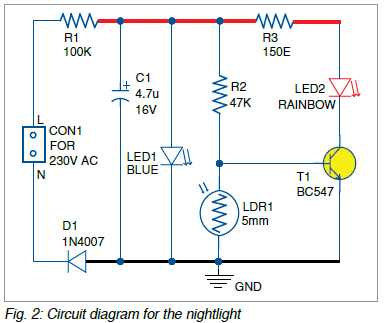

None of T.K. Hareendran’s circuits work. He has been dumping his untried, untested, junk circuits into Electronic For You magazine for years and never bothered to reply to my emails.
The 100k resistor will only allow 3.2mA to flow at the top of the wave and this will only occur every half cycle. This reduces the average to less than 1mA !!!
The blue LED drops 2.7v and so the whole circuit only has 2.7v to play with.
The drop across the collector-emitter of the transistor is 0.3v so how do you expect the blue LED in the rainbow LED to illuminate if only 2.4v is available?
But if you look at the whole project, why turn the LED on with a transistor etc when the circuit takes just as much current when not working??
The whole project is a FLOP.
What is the purpose of the 150 ohm resistor? Who cares about the diameter of the LDR?
Apart from that, the circuit is live and DANGEROUS.
Never make any circuits that connect directly to the 240v.
They are ILLEGAL in Australia and India should wake up to this situation.
He posted a video of the circuit and he thinks: “Just because the circuit works, it must be designed correctly.”
The voltage across a LED varies considerably and on some occasions, the circuit will work very faintly.
But I am criticising the lack of understanding and the lack of technical know-how and the lack of “tolerance” in the components.
I remember an Indian flip flop circuit from 40 years ago in an Australian magazine. I built it and it did not work.
I found out later that the variation in gain of the transistors needed the resistors changed to get the circuit to start working.
And the same with a micro flasher from England. I never got the circuit to work and again it relied on adjusting the components to get the circuit to start oscillating.
It’s a fluke if you can get them to work.
He posted a video of his circuit working.
The voltage across a LED varies considerably and just because a particular set of components work in the laboratory, does not mean the circuit is suitable for publishing.
You need to get your values CORRECT and UNIVERSAL - so that anyone with any set of components will be able to get the circuit working.
When I design a kit or any project, I build a number of prototypes and prove the fact that it will work perfectly because none of the components are critical.
It just separates the DESIGN ENGINEER from the dodgy ENGINEER.
THIMK !!!
Here is an OR-gate from an electronics forum:
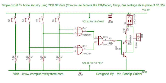
Here is a reply from a technical engineer:
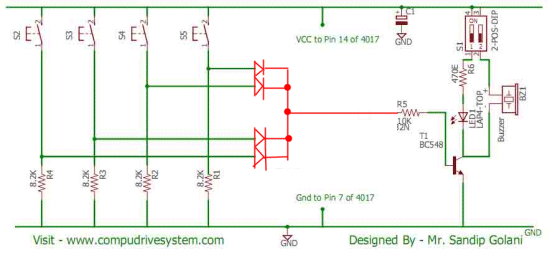
Here is my reply:
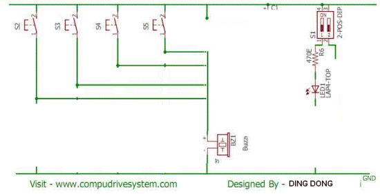
The whole point of this website is to teach you how to simplify things and think like an engineer.
Whenever your design a circuit, go through each component and ask: “Is this needed?”
Sometimes, the saving of one or more components can be the difference between profit and loss, when you are selling thousands of items.
But it also shows you are good engineer. That’s why you have to thimk !!
I received this PC board today:

It is not mine and was received by mistake from the PC board manufacturer.
But it is a good lesson for everyone.
The board has no markings or component values.
This is a big mistake.
You might think you will remember, but when you have hundreds of different PC boards and lots of different versions and improvements, you cannot possibly remember everything.
All my boards can be assembled without any further information. All the component values are shown on the OVERLAY (called the LEGEND) and the name of the project with TalkingElectronics.com identification.
Some of my customers buy a kit and don’t assemble it for 20 years. All these marking are not just for my benefit but for EVERYBODY.
A fully documented board shows professionalism as well as convenience.
We have passed the stage of paying extra for double-sided boards with a legend on top and bottom as well as plate-through holes and tinned lands. All this beauty is included for FREE.
There is no excuse for not producing a perfect board and something that someone can take way and assemble without frustration.
One of the websites provided an article on soldering.
It suggested one of the cheap soldering irons that gets “as hot as hell.”
Here are my comments:
The soldering iron kit you offer is absolutely WORTHLESS. For the same price you can get a temperature-controlled iron on eBay.
0.2mm solder is a bit fine.
0.5mm solder is the best and here is the way to set the temperature of the iron:
Turn the temperature knob down to very low and turn the iron ON.
Gradually increase the temp and wait for the tip to heat up.
When the solder begins to melt, you have reached the temperature called the MELTING POINT.
Now increase the temperature slightly so you will actually solder at a higher temperature and this will allow the solder to “run” all over the joint and not get cold.
The most important part of the solder is the flux.
It is important not to “burn the flux” but allow it to get hot and it becomes an ETCHANT and “digs away” the oxidised layer on the solder-land - just just soap on our hands.
The solder should be on one side of the wire you are soldering and the iron on the other and you should just touch the solder to achieve THERMAL CONDUCTIVITY to melt the solder and allow it to run all over the wire and the land.
This should always be one in less than ONE SECOND because sometime you are soldering LEDS and they will be damaged if it takes 2 seconds.
The website did not show any valid images on how to solder and no-where did it say to tin only one land for a surface-mount component and then place the component and “stick it in place” before fully soldering the other end and maybe coming back to the first end.
NOTE ON SOLDER:
Some Chinese solder is RUBBISH. It does not melt and the surface is not shiny.
These are the specifications to look for: 63/37 Eutectic the label with SENIOR SOLDER has been very good.
50gm or 100gm or 200gm Must be 0.5mm or 0.6mm Nothing else.
I have received 3 rolls of rubbish.
To use them I cut off 1 metre of rubbish and 1 metre of good solder and twisted them together with the electric drill and used them to solder large terminal pins. I used up the 3 rolls.
That’s why I am so careful when buying solder.
FM TRANSMITTER
You don’t mix the markings on a component with component-values on a circuit.
![]()
Sometimes I put additional component-values and component-markings on a PC board to prevent wrong values being fitted. Such as 220 for a 22 ohm surface mount resistor and 4702 for a 47k surface mount resistor.
The 223 and 102 on the circuit above should be 22n and 1n. Non-electrolytic capacitors (such as ceramic) are not identified with one thin line and one rectangular box - just two straight lines. The circuit look like it has been copied from my website as the component values are identical to the one’s I use.
You don’t need 470u across the battery because the current will be less than 10mA and 10u will be sufficient.
1uH for the coil is too large. 0.1uH (100nH) is approx correct. With this simple mistake, the circuit will never work.
A FIRST LAB IN CIRCUITS AND ELECTRONICS
This textbook is filled with mistakes and terrible descriptions as well as teaching quite complex things to beginners, without covering the really-needed basic things.
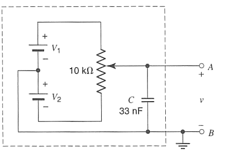
Here is a positive/negative output supply with the “batteries” identified by a single cell instead of a voltage. The output is marked ”+” and ”-” but it will be reversed when the pot is at the lowest position.
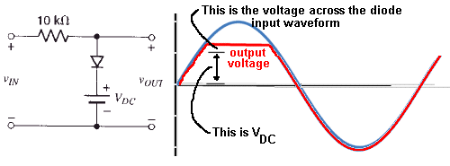
The text says: “You have made an AC to DC converter.”
The input shows DC !!!
If the input is AC, the graph shows the output voltage will follow the input but get clipped at a voltage equal to VDC plus the 0.6v across the diode.
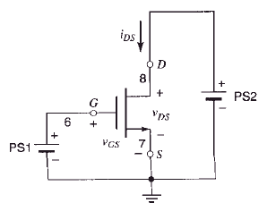
As soon as you supply sufficient voltage to the gate to turn the MOSFET on, current will start to flow and if the voltage is increased further, the MOSFET will short-circuit the power supply and either the MOSFET will blow up or the power supply will “cook.”
There is no current-limiting LOAD resistor.
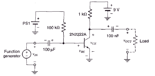
The 100u is around the wrong way. The Function generator will produce a voltage higher than the base-emitter voltage.
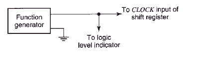
What is a LOGIC LEVEL INDICATOR?
A Logic Level Indicator is generally a LED that shows when an output is HIGH.
The term should be LOGIC PROBE because the output will be oscillating at 100Hz to 10kHz and a Logic Probe will indicate the percentage HIGH and percentage LOW, by the illumination of the LEDs and the pulse LED will show a signal is present.
He also says: We see capacitors with 1000 on them to indicate 100 with no zero’s to mean 100p.
SHOW ME WHERE ???
In his kit of parts he uses 1/2watt 10% resistors. Who uses 1/2watt 10% tolerance resistors????
The text book is an absolute DISASTER.
He has obviously never used a CRO in his life, otherwise he would have included the table:
| TIME/DIV | Frequency |
|---|---|
| 50mS | 20Hz |
| 20mS | 50Hz |
| 10mS | 100Hz |
| 5mS | 200Hz |
etc
This is the most important table for a CRO and is placed on the side of the CRO so you can quickly see what frequency is being displayed.
That’s why so many visitors to Talking Electronics website said they have learnt more from the website than all the teaching they got at University.
Here’s another stupid design:
Wireless Electricity Generator
by D.Mohankumar

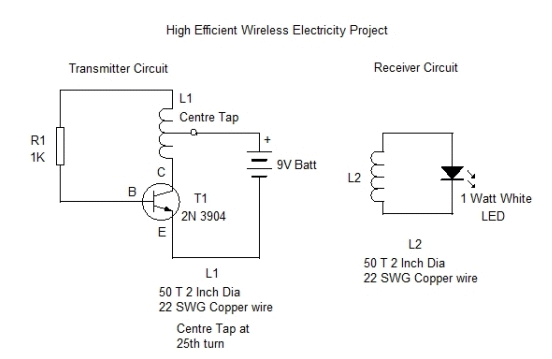

The gain of the transistor is only 30 at 100mA and the current capability of the transistor is about 100mA, so it is not suitable for the circuit. You can’t use a “100mA transistor to do a 100mA job.”
The power delivered to the LED will be about 300mW at the most. You can’t get any more than this from a 9v battery. Do you think a 9v battery is the “power-plant of the future?”
That’s only the first problem.
You will find the reverse voltage is more than the LED will tolerate.
Here is the specification:
Maximum reverse voltage between ANODE and CATHODE: 5v.
You have a 25 turn to 50 turn transformation ratio so the reverse voltage can be 18v or more.
Reverse spikes can damage a LED much faster than the blinking of any eye.
Just because a circuit works and illuminates a LED does not mean it is a good design.
The whole circuit is designed incorrectly and the turns-ratio should be 25:15 - apart from all the other mistakes.
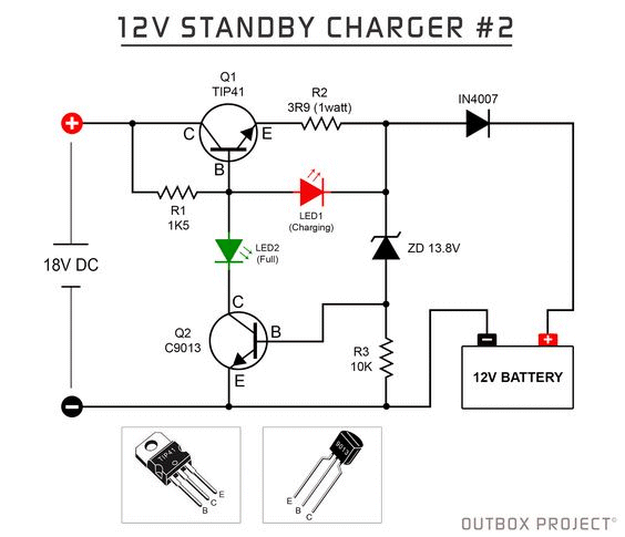
It is very complex to design a battery charger and here the problems with the circuit above.
The 3R9 1watt resistor will only allow a maximum of 500mA before the resistor will burn out.
The voltage across the collector-emitter terminals is given as 4v in the data sheet.
If you are detecting 13.8v you are not providing any “head-room” to charge the battery.
The voltage across the 1k5 will be 13.8v + 0.7v + 1.7v = 16.2v
If you have 18v supply, the voltage will be 1.8v across the 1k5.
The current through the 1k5 will be 1.2mA The maximum gain of the transistor is 100 so 120mA will flow.
If we allow 2v across the transistor the voltage drops will be 13.8v + 0.7v + 1v across the 3R9 plus 2v across the transistor = 17.5v
If the supply is 18v you have no “headroom” so that almost no CURRENT can be delivered at the low supply voltage.
It seems that only 120mA will be delivered and all you need is a resistor permanently connected to the battery and it will be trickle charged all the time.
This circuit does almost NOTHING.
It’s just a JUNK circuit.
Here’s an over-design from DIYODE MAGAZINE:
It is a temperature controller for a USB soldering Iron:
The fact is a USB socket can only deliver 5v at 1 amp. This 5 watts. 5 watts is only good for the smallest joint and will be quite unsuitable for any component that needs to be removed quickly or has large thick leads.
If you have one of these worthless irons and want to reduce the temperature, all you need is 3 x 1 ohm wire wound resistors and an alligator clip. Put them in series with one lead and connect the alligator clip to the other lead and add 1, 2 or 3 ohms to the resistance of the iron to reduce the temperature. You can also get 3R3 if you want the iron really cold to do plastic work.
For $14.00 you can get a 240v temperature controlled 20 watt iron from ebay.
For $25.00 you can get a temperature controller soldering with a base station that indicates the temperature on 7-segment displays. Everything else is either over-priced or just RUBBISH.
SOLDER
I have been using Australian-made solder for the past 60 years and never had a problem.
I though 60/40 solder made anywhere in the world would be absolutely identical to the type I have been using.
But I recently bough Chinese 60/40 resin cored solder and it was absolutely useless. I don’t know if the combination of tin and Lead was exactly correct or if some other “filler” has been included or if the “reject” metals have been added.
The solder did not melt at the normal temperature I have been using for 60 years and the solder did not “run” over and around the joint and the surface of the joint was was shiny.
No-matter what I did, the result was terrible.
I then bought eutectic solder that has the combination in the ratio of 37% to 63%. This ratio produces a solder with the lowest melting point. This solder worked much better but was still not as good as the Australian-made solder.
You must ONLY BUY eutectic solder and make sure the seller guarantees it to be eutectic as the label on the reel does not indicate this. See above for more thoughts on buying solder.
Here is a TEMPERATURE ALARM from a suppler on eBay. It is not expensive - but it does not work.
You can imagine the frustration of the hundreds of buyers having the same problem.
The supplier was not interested in the mistakes.

Here is the circuit. 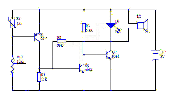
Here are the problems.
The first thing you have to know is the type of thermistor. It has a cold value of 1,000 ohms resistance.
There are two types of thermistors. One is PTC (Positive Temperature Coefficient) and its resistance INCREASES when it get hot. The other type is NTC ( Negative Temperature Coefficient) and its resistance DECREASES when it gets hot. The type used in the circuit NTC. When its gets hot, the resistance decreases to 600 ohms and less.
Now we can see how the circuit works.
The 10k 10-turn pot is adjusted so that the first transistor is turned ON. The first transistor turns ON the second transistor and the second transistor turns OFF the third transistor. This means the buzzer does not produce a sound.
When the thermistor heats up, its resistance decreases and the voltage between emitter and base of the first transistor decreases and this turns the first transistor OFF.
But the second transistor is still being kept ON via the 39k resistor and thus the buzzer does not produce a sound.
When the 39k is removed, the circuit works perfectly.
But the buzzer only gets a voltage of about 1.8v because this is the maximum voltage that will develop across a red LED.
To make the buzzer louder and prevent the red LED being damaged, a 100R should be included in one of the leads of the LED.
Finally, the circuit did not work for me because the 10-turn pot was “102” (1k) and the resistance of the thermistor did not go low enough to turn OFF the first transistor.
The CAD package use to produce the printed circuit board created a GROUND PLANE between all the tracks and a beginner could easily leave too much solder on a pad and the solder will touch the ground plane and create a “short.”
Lastly, the first and second transistors are connected from the positive and negative rails without a current-limiting resistor.
When they are both turned ON, a very high current will flow through them. This is especially the case when the supply is increased to 6v. The transistors get very hot.
Now you can see why you have to be very experienced in designing a circuit. If not, you can introduce 5 faults into a simple circuit such as this, and produce frustration for everyone who buys the kit.
I have told D.Mohankumar to stop putting his JUNK CIRCUITS on the web and messing up young enthusiasts with poor designs and circuits that do not work.
I have covered this circuit before but he continues to put it on the web.
A 1 watt LED takes 300mA at full brightness and this means 300mA will flow through the 10 ohm resistor and drop 3v.
The battery only supplies 4.5v and the drop across the transistor will be about 0.3v. The LED has a characteristic voltage across it of 3.6v when fully illuminated.
Work it out for yourself. The voltage across the resistor will be 4.5 - 3.6 - .3 = 0.7v
When 70mA flows, the voltage across the resistor will be 0.7v.
When 70mA flows through the LED, the voltage across it will be about 3.2v and thus the current will increase to about 100mA. This means the LED will dissipate about 300mW - a lot less than 1watt.
As soon as the voltage of the battery reduces, the brightness will reduce too.
It’s just a poorly designed circuit.
The charging current will be quite small - let’s see: The 4.5v transformer will produce 4.5v x 1.4 = 6.3v.
There is a drop of 2 times 0.7v across two diodes in the rectifier = 4.9v
The voltage of the battery will rise to 5v when it is charging. This means we do not have enough voltage to charge the battery.
The transformer needs to deliver 5v plus 0.7v plus 2 x 0.7v = 7.1v
Another project that has not been tried and tested.
Professor D.Mohankumar is just making a fool of himself, continuing to publish projects that simply will not work.
He may be using a transformer “made in India” and the unloaded voltage may be higher than 4v5. In this case he will get a tiny trickle of charging current through the 56R.
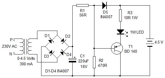
I am highlighting these faults and showing how to work out the current that will flow in the charging process and the illumination of the LED.
These values are much less than expected by Professor D.Mohankumar and that’s why it is important to do a little bit of calculating before designing a circuit, so you know if it will be operational.
In this case the circuit is a DUD.
Not only do we get a lot of bad engineering from Indian websites, but many of the world-wide electronics magazines also have terrible faults.
Here is a typical example:
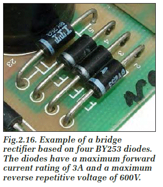
A 3-amp diode will drop about 0.7 to 0.9 to 1.1v across it when full current is flowing.
For the diodes in this bridge, it amounts to about 1.5 watts per diode because only two diodes are conducting at any one time - so the 3waats when conducting and 0 watts for the other half of the cycle amounts to an average of 1.5 watts per diode. .
The total for the bridge can amount to 6 watts and the printed circuit board simply will not dissipate this amount of heat when the diodes are closely spaced.
I have had many TV’s where 1 amp diodes on a PC board have eventually blackened the board and melted the solder and created faulty connections.
If you want long-term reliability, the board must have sufficient trackwork to keep the diodes to a point where you can hold your finger on the leads for at least 10 seconds. This involves spacing the diodes further apart - much further apart.
I am absolutely horrified that a magazine would allow a contributor to send in a construction project, showing the final design with no overlay. I would probably go further to say the board had been created with a “dalo” pen and etched with Ferric Chloride.
This means the reader has no opportunity to get the board made and really the whole project is a worthless endeavour.
There are just so many things wrong with presenting this sort of rubbish, that it makes me wonder why the publishers produce an electronics magazine in the first place.
When they do have a printed circuit board available, the cost is so high that you could buy the whole project read-made for less cost.
The subscriptions to these magazines is so small, they do not publish the figures !! Going by the number of copies in the newsagents, the sales can be counted on a few fingers. They are only crippling themselves by not catering for the beginner/experimenter and providing Printed Circuit Boards at a reasonable cost and a kit of parts.
Here’s a circuit from Electronics Monthly February 2019 - an Indian magazine with no technical staff and no understanding of circuit design:
The battery shows a single cell whereas it has to be a voltage greater than 7v for the 7805 to work.
Why include a voltage regulator. The circuit will work perfectly from 6v to 12v.
The 10u and 1u do not show the polarity of the electrolytic.
The “globe” above the 1u has no connections and no-one really knows what it is suppose to be.
R1 is 100k. (according to the parts list)
This value is FAR TOO HIGH.
To turn off the first transistor, the base voltage must be less than 0.5v
In the dark, the resistance of the LDR is very high. Normally it is about 300k.
So, let’s work it out.
Suppose the LDR goes to 100k. The voltage at the mid-point of the LDR and 100k resistor will be 2.5v. Too high.
Suppose the LDR goes to 400k, the voltage at the mid-point will be 1v. Too high. It has to go to 800k !!!
Suppose R1 is 100 ohm. The LDR will have to go to about 1k to turn ON the transistor. This is possible with a bright - focused - light.
When the first transistor is turned ON, the wasted current through it will be 50mA and the transistor will get warm. This is a bad design.
The speaker symbol is not really a speaker but an active buzzer and the diode is not needed.
When the first transistor is OFF, the base current through the second transistor is 15mA. It only needs 3mA to 5mA to operate the buzzer.
Just another badly designed circuit that should not be presented in an electronics magazine.
Here’s another disaster.
This is a PROBE intended for both TTL and CMOS circuits.
How do you use it?
A normal LOGIC PROBE had the negative lead of the probe connected to the 0v rail of the project and the TIP of the probe is used to probe all the active points of the project.
If the active point has a voltage higher than about 2v to 3v, the RED LED on the probe is illuminated. Otherwise the green LED is illuminated.
The opposite occurs on the circuit above.
You must have uniformity with TEST GEAR.
And because the LEDs are shown incorrectly, the red LED will never turn off.
The input impedance of a probe should be 1M. This effectively puts NO LOAD on a circuit AT ALL - especially when the lines are running at high frequency. .
A VERY badly designed circuit
Here’s another DIYODE MAGAZINE disaster.

The resistor symbols are too big and it makes the circuit look childish. The breadboard layout had no parts identified and these have been added by me to make the layout useful. The block diagram of the 555 might be ok to show the placement of the wires, compared to the wires on the breadboard but the whole purpose of a CIRCUIT DIAGRAM is to show the output lines of a chip in standard locations on the circuit so you can instantly see what the circuit is doing.
This is the whole purpose of an EDUCATIONAL MAGAZINE and this is where DIYODE MAGAZINE falls down completely.
Here are a couple of circuits from an Indian website. The first circuit is a traffic light. The red light should have the same ON time as the green LED. The green LED has no current-limiting resistor.
A resistor is needed to limit the current to the electret mic. The chip numbers are needed and pin 2 should not be left floating. The corrections are in RED. The circuit has so many mistakes that it may or may not work correctly. Build it and find out the mistakes yourself.
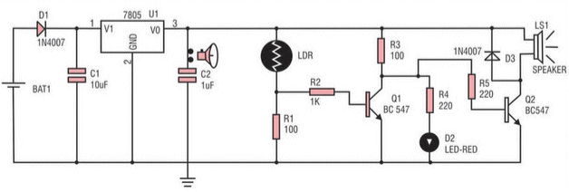
LIGHT SWITCH
Here is another junk circuit from ELECTRONICS FOR YOU.
Why is it a junk circuit?
Basically because a resistor is turning ON the relay and not a transistor.
In a correctly designed circuit, a transistor in one of the stages passes a current to the output stage to turn ON the output transistor.
A poorly designed circuit allows the resistor in the output stage to turn ON the transistor.
Let’s see why this circuit is badly designed.
If we remove the first two transistors, the output transistor will be fully turned ON.
In other words, the first two transistors simply TURN THE OUTPUT TRANSISTOR OFF !!!
Now, here’s the complex part that no-one understands.
Suppose the relay requires 100mA. Suppose the output transistor has a gain of 100.
The base current will be 1mA. The voltage across the 1k5 will be 1.5v
In other words, the output transistor will begin by not turning ON and the current through the 1k5 will be (6v/about 2k) = 3mA. This current will turn the transistor on fairly strongly and the emitter-collector voltage will be less than 1v. This will allow less than 1mA to flow through the 1k5 and the transistor will turn OFF slightly until it settles at a voltage across the emitter-collector leads that allows 1mA to flow through the 1k5.
The base-emitter voltage will be 0.6v when this occurs.
This means the circuit will lose 1.5v + 0.6v = 2.1v and the relay will get 4v from a 6v supply.
If the supply is about 10v, this loss will not matter. But it is just the wrong way to design a circuit.
Secondly, when the relay is not activated, about 10v is across the 1k5 resistor and if the circuit is battery operated, this is 7mA wasted current and a correctly designed circuit will consume less than 1mA when not activated.
Now, for the other mistakes:
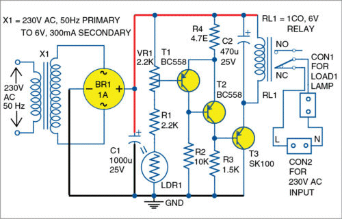
What is the purpose of R4 (4.7 ohm) ??? It serves no purpose.
What is the purpose of the 470u?? It will have 100 times more effect if placed in the second stage of the circuit.
The output transistor is an EMITTER FOLLOWER and it has a high voltage across its terminals when turned ON, compared to a COMMON EMITTER stage.
You only need 2 transistors to get the required amplification.
And finally, a qualified engineer will design a circuit according to the commonly-accepted way, so anyone looking at or fixing the circuit, will see how the circuit works.
Here’s a correctly-designed circuit:
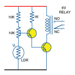
The correct way to design a circuit
This circuit is simpler, takes less current and delivers more current and a higher voltage to the relay.
You can see exactly how it works and is much easier to fault-find and fix.
There is a standard way to design a circuit and produce a diagram that all other electronics engineers will understand. If you want to use PNP transistors, simply invert the 2-transistor circuit and have the emitters connected to the positive rail. Use PNP circuit-symbols and the job’s done.
LOW VOLTAGE CUT-OFF
Here is another poorly designed circuit from Mohankumar

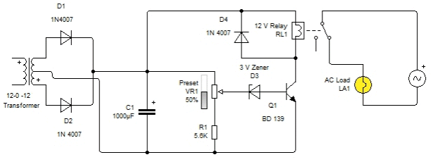
An AC transformer does not have ”+”
And it is not necessary to indicate the start of any of the windings.
1N4007 diodes are 1,000v diodes. You can specify 100v or 200v or 400v but 1,000v diodes are used when the voltage is very high.
The diode across the relay is not needed because the transistor will turn ON and OFF very slowly due to the 1,000u charging and discharging slowly and the relay will not produce any back emf.
Value of pre-set pot is not given.
3v zener diode is not needed. It makes no improvement and has no purpose.
The 5k6 resistor is in the wrong position as it needs to be above the pot to prevent the high voltage from the transformer damaging transistor.
The circuit is a COMPLETE DISASTER.
FLICKERING LED
Here is another terrible design from DIYODE magazine:
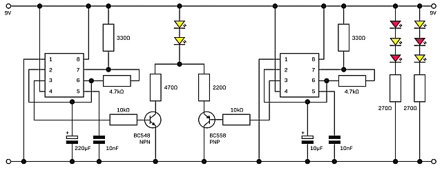
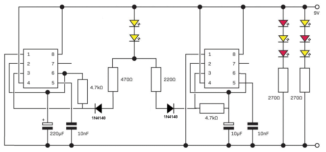
Here is a simplified version of the circuit. You do not need the two transistors as the output of the 555 will illuminates the LEDs.
I do not like the layout above as I have to try and work out the what the circuit is doing.
In the following circuit I have started to draw the two 555’s and the timing components.
I stopped when I realised the circuit is so badly designed that it is not worth finishing.
The first 555 simply turns the LED on brighter and the second 555 simply flashes it at a regular rate. This is nothing like a flickering candle.

The unfinished FLICKERING LED circuit
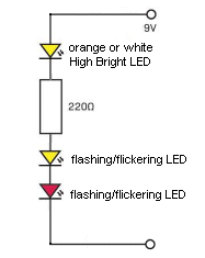
Here is a much better design and it is much simpler. It only needs two flickering/flashing LEDs in series with the high bright LED and the result is the combination of the effects of the two flashing LED. You do not need the 220R resistor as the flashing LEDs have inbuilt resistors. This gives a really random flickering effect.
It is pointless using 15 components to perform an effect that only needs a few components.
You can buy a flickering candle LED from Talking Electronics.com for 10 cents.
It has an inbuilt resistor and works from 4.5v to 6v.
If you are going to do something, do it PROPERLY.
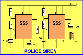
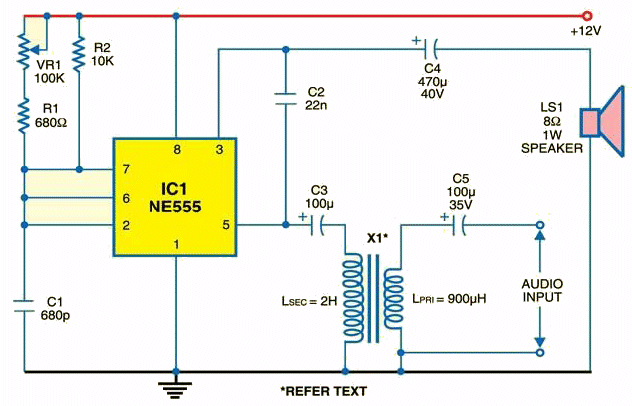
POLICE SIREN
Here is another design from DIYODE magazine, that needs improvement: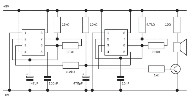
The 555 IC has the capability of driving a speaker via a 10u electrolytic and the transistor is not needed.
Why use a 470u electrolytic when a 100u can be used, providing the resistor is increased to 10k.
That is the purpose of the 10k resistor, connected to the 470u electrolytic?
When the circuit is drawn with the pins in the correct positions, you can see exactly what the circuit is doing.
SOLAR STREET LIGHT


Why is this design so inefficient?
The specifications are very deceptive.
Their advertisement is vague, dishonest and deceptive.
The facts and figures are these:
There are 6 panels around the post and the total output of all the panels is 100 watts.
This is 16 watts per panel.
Only one will get direct sunlight and 2 will be at 30 degrees to the direct rays of the sun. The two side panels will produce about 15% less, according to this accurate website:
https://www.civicsolar.com/support/installer/articles/solar-array-tilt-angle-and-energy-output
This gives 16 + 14 + 14 = 44watts.
But the angle of incidence must also be taken into account because the panels are vertical and sun is high in the sky. The rating must now be de-rated by another 15% to 20% making the maximum output about 35 watts.
However we do not know if the 100watt rating has been determined in the laboratory with direct sunlight and the final result is a mystery.
The only thing we know is 100 watt (direct) becomes 35 watts in reality.
Allowing 5 hours per day, this is sufficient for a 50 watt LED light for a few hours each night.
A 100watt incandescent globe produces 1800 lumens. (A 50 watt LED light produces 5,000 lumens, so it is equal to 250watt globe).
A 12v 20 A-hr battery will store the energy. ($40.00) or (2 x 10A-hr batteries).
The lights are far too high. By reducing the height by half, the brightness will increase 4-fold. Some parks have low wattage lights at 3 metres and they are much-more effective.
This design is really inefficient and I am surprised no-one has picked up the ineffectiveness.
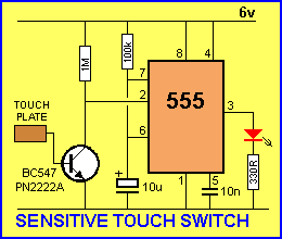
Piezo Touch Switch
Rob Bell & Daniel Koch Issue 11, May 2018
Another poorly designed circuit for DIYODE Magazine.
The writers have have absolutely no idea about designing an electronics circuit.
What is the purpose of the 1k, connected to the piezo diaphragm? The diaphragm has an almost infinite impedance and 1k is not going to make any different !!
Why use an op-amp when a simple transistor will do the job ??
This diagram is half-circuit and half component layout. The Piezo “block” should just show the symbol of a piezo diaphragm and the leads to the relay should show the connections to the relay as I have no idea where the 3 leads are connected. A circuit diagram is not intended to produce FRUSTRATION and “guess-work.” It must show all the details instantly.
What impact will 10n on pin 5 have? Pin 5 is low impedance (less than 5k)
On the PCB, there is no legend and you don’t know where to put the components.
The worst type of board for beginners has the earth plane all over the board. The slightest mistake with soldering can cause a short-circuit.

Soldering to the board like this is not a standard concept for a simple circuit. This type of construction is kept for very high frequency circuits where the ground plane separates the components from interaction between different sections.
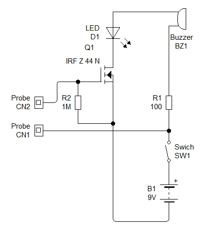
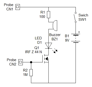
Just an over-designed project that could be created with fewer components, as shown below:
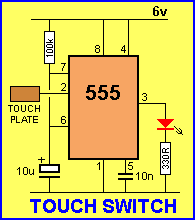
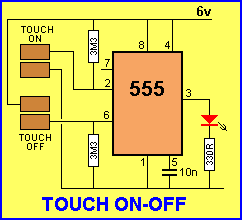
The circuit can be made 100 times more sensitive by adding a transistor to the front-end as shown in the diagram below:
Before designing a project, DO YOUR HOMEWORK and look on the web for suitable circuits.
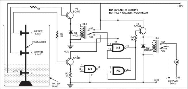
WATER TANK ALARM
Here is another poorly designed circuit from Mohankumar
Why use a 49 amp MOSFET to deliver 10mA???
His circuit diagram is so poorly laid-out that I could not see what was happening.
It has been re-drawn correctly.
MOSFETs are expensive and a simple high gain transistor or a Darlington pair could be used in place of the MOSFET.
FIRE ALARM
This poorly designed circuit comes from Electronics Maker Magazine - India
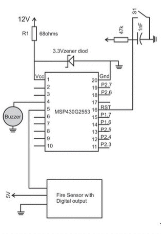
The 68R resistor allows 130mA to flow through the 3v3 zener. The microcontroller only needs a maximum of about 20mA, so this “bleed current” could be reduced to 50mA. It’s just a matter of designing things so you don’t get any criticism. The resistor is losing over 1 watt and the zener over 400mW, so both have to be carefully chosen.
PCB Manufacturing Workshop for Engineering - Skyfi Labs
More RUBBISH from Indian educational courses.
The heading clearly states PCB Manufacturing for Engineering.
But when I contacted Skyfi Labs, they said the course was for “students”
The course costs between 3 and 4 days pay for the average Indian (equal to $300 Australian) for a JUNK paper-based PCB with no overlay, bare copper lands and no tinning.
It is really something that has disappeared 40 years ago and and not only is the layout terrible, with the spacing of the components, but the board is far too large and it doesn’t teach the student anything that is relevant to today’s technology.
I looked through Skyfi Labs other projects and they were similarly lacking any sort of up-to-date features and were enormously expensive. You have to consider the average day’s wage for an Indian is only a few dollars and to charge 3 day’s wages to make this piece of RUBBISH is a RIP-OFF.
The student would be better to buy his own soldering iron and tools and make ten Talking Electronics Projects. At least he would be working on fibre-glass, with a legend that identifies each component and the name of the project. He would have something he could show to his new boss and give the impression he is capable of doing something. What do you think a boss is going to think about this:

You have to “think outside the square” and think: WHAT A WASTE OF MONEY
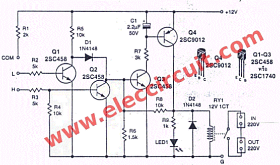
WATER PUMP CONTROLLER
Here is another poorly designed circuit from Electronics For You Magazine:
Let’s look at this terrible design.
The two detecting transistors are emitter followers and to get enough current to flow into the base, the top transistor needs 0.5mA. This means the resistance of the water must be 24k. Water has an accepted resistance of 70k for this type of circuit, so this is the first mistake.
Why do you need a relay to activate the input of a NAND gate??
Why do you need a diode across the relay when the circuit will gradually increase and decrease in current?
Here’s a circuit that uses fewer components and almost any NPN and PNP transistors can be used.
7-SEGMENT DISPLAY
More mistakes from Electronics For You Magazine:
There are basically 2 types of 7 segment LED display:
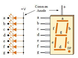
Common Anode: All the Negative terminals (Anode) of all the 8 LEDs are connected together. All the positive terminals are left alone. This is INCORRECT. The anodes are connected together and taken to 0v. The cathodes are taken to a positive voltage such as a drive-line. (The anodes are NOT negative)
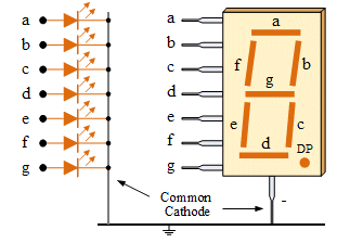
Common Cathode: All the positive terminals (Cathode) of all the 8 LEDs are connected together. All the negative thermals are left alone. This is INCORRECT. The cathodes are connected together and taken to 0v. The anodes are taken to a positive voltage such as a drive-line. (The cathodes are NOT positive)
Don’t say the Cathode is positive or negative (or a positive terminal) because it depends the device you are referring to.
For instance:
In a galvanic (voltaic) cell, the anode is considered negative and the cathode is considered positive. This seems reasonable as the anode is the source of electrons and cathode is where the electrons flow. However, in an electrolytic cell, the anode is taken to be positive while the cathode is now negative.
Just say the cathode is taken to the positive rail or the negative rail, depending on what you want the LED or diode to do. For instance, the anode of zener diode is taken to the 0v rail and the voltage appearing on the cathode will be zener voltage for the device.
PROBE
More mistakes from Electronics For You Magazine:
Here’s a badly designed circuit for a simple LOGIC PROBE:
When nothing is connected to the input, the red LED illuminates WHY ???
A LOGIC PROBE normally has the negative lead connected to a project under test and the other probe touches different parts of the project.
If you connect the black probe to the 0v rail of a project and touch the red probe on the 0v rail, the green LED illuminates. If you touch the red probe on a rail that is 6v, the green LED remains illuminated. The green LED does not turn off until the input voltage is above 9v !!!!
Another disastrous project that has not been tested.
LED FLASHER
This circuit can be simplified, made smaller and cheaper by using transistors:
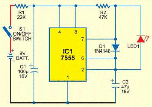
The following two circuits flash the LED very brightly and if the supply is 6v, a white LED can be used:
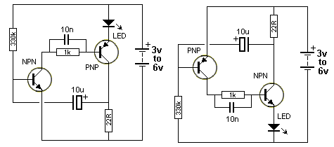
The two circuits are identical. The second circuit is simply “up-side-down” to show how you can do this.
LED TORCH
You don’t stop a circuit working by TURNING ON A TRANSISTOR FULLY to prevent it from operating.
If you want to turn a circuit OFF - you turn the transistor OFF by reducing the voltage on the base. The transistor will then consume NO CURRENT and the circuit will stop working.
In the circuit above, the voltage on the 1k resistor (R5) increases and the LEDs illuminate. When the voltage reaches 1.2v, the voltage on the base of the transistor will keep it in saturation and it will stop oscillating. This condition may only be for a short period of time but it is the wrong way to control a circuit.
The current through the 1k will be 1.2mA and this is very low for a LED TORCH CIRCUIT.
Just a terrible design.
AUDIO AMPLIFIER
This is supposed to be an audio amplifier working on 100kHz PWM frequency. If pin 3 output at 100,000Hz, the impedance of the 470u will be less than 1 ohm and the total resistance will be less than 10 ohms. One amp will try and flow and the chip will explode !!!
NIGHT LAMP
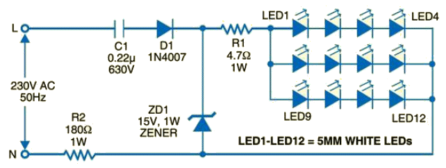
A 0.22u capacitor will deliver 3mA in half-wave and when this is divided between 3 strings of LEDs, each will see 1mA. This is not sufficient to get any sort of illumination out of a high-brightness white LED.
The circuit simply will not deliver any brightness.
FREE ENERGY
Here’s another one of those FREE ENERGY schemes. But instead of saying FEE ENERGY they make absurd claims that the solar panels in the following zig-zag frame produce 2 times more energy than flat panels and up to 20 times more energy.
The heading to this fraud is:
MIT BREAKTHROUGH DISCOVERY HELPS YOU SAVE 65% ON POWER BILLS! STARTING NOW!!!


They try and say your power bill be halved. And yet the multimeter reading is just 13.6v.
No current measurement is taken.
Of course the 10 panels will deliver up to 1 amp to charge the battery over a period of 6 days, but that is completely insufficient for a house or even a tent !!!
And they want to charge you $39.00 for a download to make the wooden frame and wire the panels.
You can get all this from the web for FREE !!!
The very first electricity fraud was: CUT YOUR ELECTRICITY BILL IN HALF. Send $5.00 for full details.
They sent you a small pair of plastic scissors !!!
Why do car batteries fail?
There is a lot of false information on the web about rejuvenating any type of rechargeable battery - especially car batteries.
The reason why a car battery fails is unknown.
It can be working perfectly for 2 years and you park the car for 30 minutes and the car fails to start.
It can be as sudden as this.
Some batteries last for 12 years, some for 1 year.
A car battery has 6 cells and one cell nearly always fails and the battery is worthless.
WHY?
The reason is due to SELF-DISCHARGE and INTERNAL DESTRUCTION.
The plates of a cell are made in the form of a grid from lead and a strengthening material. Don’t worry about any of the chemical names. The holes in the plate are filled with paste and this paste also contains lead.
The liquid in the battery is called the ELECTROLYTE and it is SULPHURIC ACID with some water added.
The sulphuric acid is heavier than water and the two form a solution with the density slightly greater at the bottom.
This forms a cell with the voltage slightly higher at the bottom and the energy in the plates at the bottom of the cell passes through the electrolyte to the top of the cell and it gradually discharges the cell. This can be from 1% to 15% per month.
That’s why a fully charged battery can be flat after 6 months.
Put lots of salt in hot water and watch. As it cools, salt crystals form on the bottom. This is called CRYSTAL GROWTH.
When a battery discharges, sulphate crystals form on the plates (from the sulphuric acid) and these crystal have a high electrical resistance.
When you charge the cell, these crystals dissolve back into the electrolyte.
Every time you charge and discharge, these crystals form and dissolve. But if the charging is insufficient each time, the crystals gradually grow.
These crystals get between the plate and the paste in each cavity.
It makes the paste less effective and it makes the battery less responsive to charging.
All batteries cost the same to manufacture. They all use the same materials.
The life of a battery nearly always depends on it “cyclic use.”
This includes the daily temperature and the current and the number of seconds needed to start a car.
Finally, the life depends on the voltage of the regulator.
A Maintenance Free battery has no “filler holes” and you cannot add water. It has a different plate structure and does not start to produce bubbles of gas when charging until the battery voltage reaches about 15v. If the charger stops at 14.6v, the battery gets fully charged and no bubbles are produced.
Bubbles of gas are actually bubbles of hydrogen and bubbles of oxygen from the water and thus the water disappears.
HOW TO TEST A CAR BATTERY
The only way to test a battery is called a LOAD TEST.
You can do this yourself.
Pick a cold morning and start the car. If it turns over very slowly, the internal resistance of the battery is high.
We are talking about milliohms, but a starter motor will take 150amps to more than 450 amps, depending on the size of the battery and the size of the engine as well as the temperature of the day. Starting the car puts the heaviest load on the battery.
You know how fast the car should start and if it is slow, the battery should be replaced.
The standard test is to load the battery to 50% of its CCA rating (Cold Cranking Amperes) for 15 seconds. If the voltage reads above 9.6 volts the battery is ok. For example a battery that has a CCA rating of 600 should be tested at 300CCA for 15 seconds.
To put this in simple terms, start the car for a few seconds and read the voltage of the battery at the same time with an accurate digital meter. It the reading is below 9.6v, the battery is starting to reduce in current-delivering capability.
As I said before, the battery can fail COMPLETELY the next day.
I know. I am constantly jump-starting my tenants cars. And sometimes they are “miles away!”
JUMPER CABLES AND JUMP STARTERS


JUMPER CABLES JUMP STARTER pack
You should always carry a set of jumper cables in the car, in case you need to JUMP START your car.
These cables can be as cheap as $25.00 on the web or $35.00 from Automotive stores.
You can also invest in a JUMP STARTER pack costing as little as $49.00 on the web to more than $220.00
These must be “topped up” every month with a short charge to make sure the battery is fully charged.
The only reason why it works is due to the fact that the battery in the JUMP STARTER is fully charged and produces a voltage of 12.6v.
When you connect the JUMP STARTER to your battery, it will start to charge your battery and raise the voltage slightly.
When you try to start the car, the JUMP STARTER will raise the voltage to the starter motor and the starter motor will take more current. This means the starter motor will be more powerful and the car will “turn over.” (start). Both batteries will share the current - not 50:50 but according to the internal impedance of each battery and the resistance of the leads to each battery.
Even a partially charge battery (called a “flat battery”) will deliver a high current. But the voltage of the battery decreases when it is “flat” and thus the starter motor will not take a high current. But if we can raise the voltage of the “flat” battery, a high current will delivered to the starter motor. This is what the JUMP STARTER pack does. It produces what is called a FLOATING CHARGE or FLOATING VOLTAGE when it is connected to the flat battery and within a few seconds the voltage of the flat battery will be very close to 12v. It is the CURRENT that produces the horsepower and a higher current allows a higher current to flow.
The voltage delivered to the starter motor is very important because each volt INCREASE allows a HIGHER current to flow and the torque (twisting effect) produced by the starter motor INCREASES considerably.
Suppose the starter motor produces one horsepower when the battery is 12.6v. The voltage of a good battery will drop to 11.5v when starting the car and may be slightly less than this due to the resistance of the leads to the starter motor.
When it drops to 10v, the starter motor produces 0.8 horsepower and at 9v it produces 0.6 horsepower. That’s why the car will not start.
Basically, if you double the current you get 4 times more horsepower. This also means: If you double the voltage you double the current and thus you increase the horsepower 4 times.
In addition, at 9v to 10v the battery will not provide sufficient voltage for the ignition coil to produce 20,000 volts for the spark-plug and so you have another problem.
HOW TO USE JUMPER CABLES
Connect the jumper cables and see if there is a spark when you connect them. A spark indicates your battery is very flat.
Start the other car and increase the RPM for a few minutes.
Turn off the ignition and then try to start your car.
Do not try to start your car when the other car is running. The load you are putting on the generator may damage it, especially the set of stud diodes or the voltage regulating system.
If the car does not start, try again after another 5 minutes of running.
With the JUMP STARTER pack, you only have one chance to start your car.
Connect the JUMP STARTER and wait 5 minutes. Then start your car. This gives the JUMP STARTER a small amount of time to charge your battery and is called a FLOAT CHARGE.
CLEARING UP A MYTH
Let’s go over the concept of a JUMP STARTER pack and JUMP CABLES again.
When you connect two batteries with Jumper Cables, the voltage of the “good battery” will very quickly increase the voltage across the terminals of the “flat battery” and this voltage is called a FLOATING VOLTAGE. The good battery may charge the dead battery a small amount and deliver a few amps to charge it but the charging current will be very small because the voltage of the good battery is not higher than 12.6v and this is not high enough to deliver a high current.
If you start the “good car,” the voltage from the alternator will be over 14v and both batteries will get charged and share the charging current and this can be as high as 30 to 40 amps. The flat battery will get most of this current.
But don’t think the good battery is doing all the work of starting the dead car. The voltage drop in the jumper cables and the poor connections of the alligator clips will create voltage-drop of a few volts when 250 amps is flowing and the car will not start if the flat battery is not present.
The good battery is simply increasing the voltage across the flat battery and this rise in voltage will allow more current to flow to the starter motor and thus it will produce more torque and the engine will start.
The whole thing that is lacking in this demonstration is VOLTAGE. The dead battery will still deliver a very high current but the current it will deliver is determined by the voltage - called the TERMINAL VOLTAGE - the voltage on the terminals.
By starting and running the good car for a few minutes, the flat battery will get a “float charge” on the plates and this will allow the car to start.
With a JUMP STARTER pack, you do not have the advantage of creating a very good “float charge” on the plates because it will not deliver very much “float charge energy” and you only have one opportunity to start the car.
SO, WHAT HAPPENS?
When you connect the jumper leads and start the “dead” car, the voltage of the battery in the good car produces a “floating voltage” - up to 12.6v and when you try to start the dead car, this voltage will reduce but it will still be higher than the voltage of the flat battery and this higher voltage will allow more current to flow. A small current will come from the good battery but the flat battery will deliver most of the current as the leads from the battery to starter motor are very short. The length of the jumper leads are 10 times longer and the voltage drop across them will be quite significant. That’s why an amazing thing happens called CURRENT SHARING. The high current required by the starter motor will create a high voltage drop in the leads and this will reduce the voltage to the starter motor and it will take less current and thus the voltage from to good battery will increase and the current will increase. This happens enormously quickly and the car starts.
After reading this discussion you can see a JUMP STARTER PACK is badly designed. It needs to be a voltage higher than 12.6v so it will deliver a FLOATING CHARGE to the flat battery and be able to deliver a high current when required. The leads to the Jump Starter pack have a resistance that will reduce the supplied voltage by one or two volts and if the battery has a voltage higher than 12.6v, the resulting voltage to the starter motor will be HIGHER.
The JUMP STARTER Pack using SUPERCAPS is worthless. The energy contained in the caps between when they are fully charged and to a voltage of say 9v, is very small (about 5%) (look at the discharge curve of a capacitor and you will see why) and this sort of Jump Starter is not worth buying. It simply DOES NOT WORK. We have already described this type of Jump Starter Pack and shown it to be a failure.
After reading this article: ANSWER THIS: Does a JUMP STARTER pack supply current or voltage or both?
Answer: A JUMP STARTER pack supplies voltage and the higher voltage (higher than the flat battery) allows the starter motor to draw a higher current and this current comes from both the flat battery and the Jump Starter pack.
Here’s how to see it working:
When the Jumper Leads are connected, the voltage across the flat battery rises and the starter motor sees this voltage and it “takes” (draws) a high current. This high current will produce a voltage-drop in the cables and across the plates of each cell in the good battery and the voltage delivered to the starter motor will drop. But it will still be higher than from the flat battery. It is this CURRENT that produces the torque required to start the car.
OLD-STYLE BATTERY
If you have an old-style battery with removable plugs to add water, if one of the cells is low, the cell is faulty and GASSING. This means the cell is producing hydrogen and oxygen gasses and is losing water (because water is made from Hydrogen and Oxygen).
Topping it up may help because as the water level falls, the plates become exposed and the cell cannot deliver full current and may be the cause of the car failing to start.
It could also be due to one of the other cells being faulty and this will make the charging voltage too high for the battery and the cell that is low in water will start to gas. There are lots of very unusual effects that can cause a battery to fail after one or two years.
Because a battery is so important and so cheap to replace, it should be replaced after the first failure.
I have learnt my lesson 3 times and now I don’t take any risks. The first time the car starts to fails to start quickly is an indication to get a new battery immediately.
https://rustybolt.info/wordpress/?p=1222
2012-02-16 Amplified Ear & Hearing Aid

I found this schematic of a hearing aid on a newer website called Talking Electronics, and it looked familiar. I checked the one on RedCircuits.com, and found that they are identical, other than the copycat has gone to some lengths to pretty it up with color and graphics. I know that this particular schematic has been around since before the website was called Red Circuits, because years ago I built this circuit and put it into an Altoids tin and I still have it today. Either one or the other of these websites has stolen it from the other, and my bet is that Redcircuits had the original, because of what I just said. I think I built the circuit long before the Talking Electronics was around.
The writer at “rustybolt” and at “redcircuits” have NO IDEA how to draw a circuit.
Instead of using R1 R2 etc, including the component values on the diagram allows you to visualise and understand HOW THE CIRCUIT WORKS.
Neither of the two authors have any understanding of electronics and that’s why Talking Electronics is so far ahead with its EDUCATIONAL APPROACH.
Looking at the red-circuits diagram does not give me any information as to how the circuit is biased and how each of the stages operate.
The red-circuits diagram is WORTHLESS and that’s why it was redrawn so that I can understand what is happening and at the same time, deliver this information to my millions of visitors.

Quick Links
Legal Stuff
Social Media