

Table Of Contents
<script language="JavaScript">
  var ans = new Array()
  var done = new Array()
  var score = 0
  ans[1] = 'The diode is ok, anode on left'
  ans[2] = 'The diode is faulty - open circuit'
  ans[3] = 'The diode is faulty - short circuit'
  ans[4] = 'The diode is ok, cathode on left'
  ans[5] = 'The diode is faulty - it is leaky'
  ans[6] = 'The diode is faulty - open circuit'
  ans[7] = 'The diode is faulty - it is leaky'
  ans[8] = 'The diode is ok, cathode on left'
  ans[9] = 'The diode is ok, anode on left'
  ans[10] = 'The diode is faulty - short circuit'

  function Try(question, answer) {
    if (answer != ans[question]) {
      if (!done[question]) {
        done[question] = -1
        window1 = window.open(
          '',
          'NewWindow1',
          'toolbar=no,directories=no,menubar=no,scrollbars=no,top=475,left=25,width=320,height=20'
        )
        window1.document.writeln(
          '<title>Answers to:  50 QUESTIONS  .   .   .   . </title>'
        )
        window1.document.writeln(
          '<font face=Arial size=2 color=#FF00cc><center>Wrong!\n\nYour score is now: ' +
            score +
            '<font face=Arial size=2 color=#cc0000><center>The correct answer is: <font face=Arial size=2 color=#000000>' +
            ans[question]
        )
      } else {
        alert('You have already answered that question')
      }
    } else {
      if (!done[question]) {
        done[question] = -1
        score++
        alert('Correct!\n\nYour score is now: ' + score)
      } else {
        alert('You have already answered that question')
      }
    }
  }

  function Assessment() {
    if (score >= 10) {
      alert('Perfect Score!')
    }
    if (score >= 8 && score <= 9) {
      alert('Excellent Work - but not Perfect!')
    }
    if (score >= 0 && score <= 7) {
      alert(
        'Your test results are not good enough. \nRead the diode testing \nprocedure again.'
      )
    }
  }
</script>

<script language="JavaScript">
  // hide script from old browsers
  // browser test:
  browserName = navigator.appName
  browserVer = parseInt(navigator.appVersion)
  if (browserName == 'Netscape' && browserVer >= 3) version = '1'
  else version = '2'
  // preload images:
  if (document.images) {
    Voff = new Image(165, 200)
    Voff.src = 'images/Diode-fig4.gif'
    Von = new Image(165, 200)
    Von.src = 'images/Diode-fig4-comp.gif'
  }

  if (document.images) {
    Q1off = new Image(165, 155)
    Q1off.src = 'images/Diode-Q1.gif'
    Q1on = new Image(165, 155)
    Q1on.src = 'images/Diode-Q1-comp.gif'
  }

  if (document.images) {
    Q2off = new Image(165, 155)
    Q2off.src = 'images/Diode-Q1.gif'
    Q2on = new Image(165, 155)
    Q2on.src = 'images/Diode-Q2-comp.gif'
  }

  if (document.images) {
    Q3off = new Image(165, 155)
    Q3off.src = 'images/Diode-Q1.gif'
    Q3on = new Image(165, 155)
    Q3on.src = 'images/Diode-Q3-comp.gif'
  }

  if (document.images) {
    Q4off = new Image(165, 155)
    Q4off.src = 'images/Diode-Q1.gif'
    Q4on = new Image(165, 155)
    Q4on.src = 'images/Diode-Q4-comp.gif'
  }

  if (document.images) {
    Q5off = new Image(165, 155)
    Q5off.src = 'images/Diode-Q1.gif'
    Q5on = new Image(165, 155)
    Q5on.src = 'images/Diode-Q5-comp.gif'
  }

  if (document.images) {
    Q6off = new Image(165, 155)
    Q6off.src = 'images/Diode-Q1.gif'
    Q6on = new Image(165, 155)
    Q6on.src = 'images/Diode-Q2-comp.gif'
  }

  if (document.images) {
    Q7off = new Image(165, 155)
    Q7off.src = 'images/Diode-Q1.gif'
    Q7on = new Image(165, 155)
    Q7on.src = 'images/Diode-Q5-comp.gif'
  }

  if (document.images) {
    Q8off = new Image(165, 155)
    Q8off.src = 'images/Diode-Q1.gif'
    Q8on = new Image(165, 155)
    Q8on.src = 'images/Diode-Q4-comp.gif'
  }

  if (document.images) {
    Q9off = new Image(165, 155)
    Q9off.src = 'images/Diode-Q1.gif'
    Q9on = new Image(165, 155)
    Q9on.src = 'images/Diode-Q1-comp.gif'
  }

  if (document.images) {
    Q10off = new Image(165, 155)
    Q10off.src = 'images/Diode-Q1.gif'
    Q10on = new Image(165, 155)
    Q10on.src = 'images/Diode-Q3-comp.gif'
  }

  function show(imgDocID, imgObjName) {
    if (document.images) {
      document.images[imgDocID].src = eval(imgObjName + '.src')
    }
  }

  // end hiding --->
</script>
THE DIODE SYMBOL
The diode symbol is very similar to an arrow touching a “bar”. The “bar” is the cathode and this is the end we refer to when describing a diode.
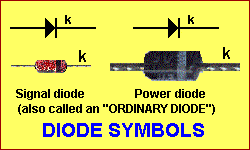
TYPES OF DIODE
There are three main types of diodes:
- The signal diode (ordinary diode)
- The power diode, (ordinary diode) and
- The zener diode … plus lots of specialized types.
The Zener diode is covered separately.
In this section we will cover the “ordinary” diode.
DIODE OPERATION
The ordinary diode has a single feature. It only allows current to flow in one direction. This is called the forward-bias direction, when the voltage on the anode is higher than the cathode. The flow of current is in the direction of the arrow on the symbol.
When the diode is in the reverse-bias direction (when a high voltage is connected to the cathode lead and the anode is connected to the 0v rail) the diode exhibits a very high resistance and no current flows.
The diagram below shows the diode in forward-bias:
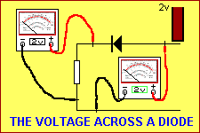
No current flows through the diode until 0.7v is on the anode and any voltage above 0.7v appears on the other end of the diode. Thus we say the diode has a 0.7v drop across it and this voltage does not change from one diode to another or due to the current flowing. (We are discussing silicon diodes. Germanium diodes have 0.2v across them and Schottky diodes have 0.3 to 0.4v across them).
If the diode is reversed, it will be in reverse-bias mode and no current will flow. This is shown in the diagram below:
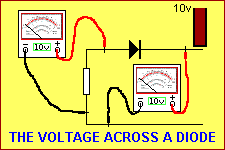
Note: The supply is on the right-hand-side of the circuit - this is the normal way a power supply is drawn - and the arrow on the diode is “opposing” the flow of current.
TESTING A DIODE
Diodes can be tested with a multimeter set to HIGH OHMS range.
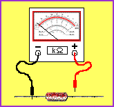
Inside the multimeter is a battery (1.5v or 3v) and this provides the energy to move the needle. One very important point to note is the red probe of a multimeter is connected to negative of the battery (inside the multimeter) and the black probe is connected to the positive of the battery (via a set of resistors and the meter-movement itself).
When the black probe is connected to the anode of a diode and the red probe to the cathode, as shown in the animation below, the needle moves about 90% across the dial. (It does not move fully across because the multimeter is actually detecting the voltage-drop of 0.7v of the diode and not its actual resistance - but this is a technical point).
When the red probe is connected to the anode and the black probe to the cathode, the needle does not move at all.
In the first case the diode is forward biased and current flows. In the second case the diode is reverse biased and no current flows. The pointer (needle) clearly indicates these two states. These are the two conditions we need to remember.
<!-- TODO FIXME: add OnHover HoverImage Component here -->
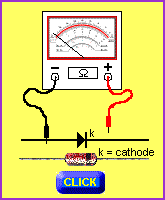
Click = mouseover
Note: the multimeter is on “x1k” scale
FAULTS
If the needle does not move in either test, the diode is faulty - OPEN!
If the needle moves slightly in the reverse-bias test, the diode is LEAKY and should not be used.
If the needle moves fully across the dial, the diode is faulty - SHORTED!
HOW A DIODE WORKS IN A CIRCUIT
Even though a diode performs only one action (to allow current to flow in only one direction), the surrounding components in a circuit will create a lot of different effects.
The simplest use for a diode is to convert AC to DC. AC is the name we give to a waveform that rises and falls in a smooth action. (Its technical name is Alternating Current but we also refer to AC as an alternating voltage). DC means Direct Current and this is the type of waveform obtained from a battery. We also refer to a fixed voltage as DC. In the diagram below we see the AC voltage rising and falling. AC is the type of voltage we get from the “mains.”
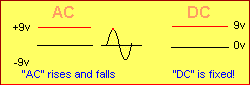
An example of “AC” and “DC”
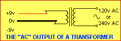
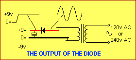
When we put a transformer on the mains, we can obtain an AC voltage, that has the same shape as the 120v or 240v “mains,” but a lower value. In the diagram below one line of the secondary of a transformer is connected to the 0v rail of a project and the other line rises 9v above and 9v below the 0v rail as shown in the animation below. The 0v rail is also called “earth.”
If we connect a diode to the line that rises and falls, the output of the diode will only contain the positive portion of the waveform, as shown in the animation below. This is because the diode only allows voltage above 0.7v to pass through it.
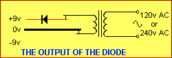
This process is called RECTIFICATION and the output of the diode consists of only the positive portion of the waveform as shown below:
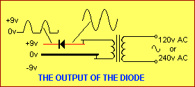
By adding an electrolytic to the output of the diode, the positive pulses will be turned into a smooth voltage of approx 9v - 0.7v = 8.3v The electrolytic charges up during the first pulse and it stores the voltage so that the waveform does not fall. This is shown in the diagram below:
If current is delivered by the circuit above, the energy (current) is taken from the electrolytic and the voltage across it drops slightly until it is charged again by the diode in the next cycle.
The circuit above is called a half-wave rectifier as only the positive portions of the waveform are delivered to the output.
An improved design is called a FULL-WAVE rectifier and both the positive and negative portions of the waveform are delivered to the output.
This requires 4 diodes in a BRIDGE arrangement as shown below.
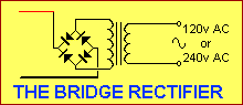
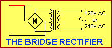
The layout of the 4 diodes (the bridge) is very easy to remember as each diode faces in the direction of the flow of energy, and so a single diode can be shown for the bridge, as shown below:
The animation below shows that only two diodes at a time transfer energy. Two diodes transfer the positive portion of the waveform then the other two diodes deliver the negative portion of the wave. Watch the output voltage rise and fall as the voltage is traced out on the sinewave. Note how the diodes change from one set to the other as the AC voltage changes from one direction to the other.
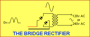
The result is the output consists of peaks that are closely spaced and the job of smoothing out these peaks is done by an electrolytic.
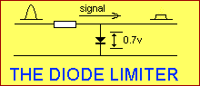
THE DIODE AS A LIMITER
A diode can be used to limit the amplitude of a signal, as shown in the diagram below. Since a diode does not turn on until 0.7v, any signal below this value will pass from the left-hand-side of the circuit to the right side. Any waveform above 0.7v will be “clipped” or “limited” by the diode and this will cause “distortion”. This distortion may be wanted, such as “FUZZ” in a guitar amplifier. The diode also has the effect of converting sinewave signals into a square wave.
THE DIODE AS A PROTECTOR
The diode can be used to protect a project from reverse-voltage and over-voltage. Here are 3 arrangements.
- A project can be protected from reverse voltage by placing a diode on the positive input line. The diode must be capable of handing the input current. The only disadvantage of this design is the 0.7v drop across the diode.
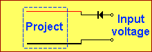
Adding a diode to the input line
- If the project is operating from a 12v car battery, for example, the 0.7v loss can be overcome by placing a zener across the input as shown below.
The zener must be a high current type as a reverse voltage or over-voltage will cause the zener to conduct and the high current is designed to blow the fuse.
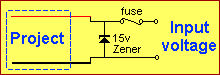
Connecting a zener across the input
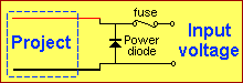
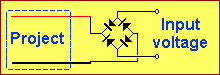
- If you only require reverse-voltage protection, a diode can be placed across the input as shown below. The diode must be a power diode such as 1N 5404.
If you want to be able to power a project via a DC voltage that is connected EITHER WAY! you can use the very clever circuit below. The only disadvantage is a loss of 1.2v across the two diodes that come into operation when the DC voltage is applied.
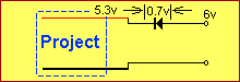
If you want to power a 5v microprocessor project from a 6v battery (such as a lantern battery or 4 AA cells), a diode can be placed in the positive line to drop 0.7v. The remaining 5.3v is an ideal voltage for a micro project. The diode also serves to prevent reverse-polarity connection.
THE DIODE BRIDGE
Many projects use 4 diodes in a bridge arrangement in the power supply and if the current requirement is fairly high, (1 amp or more) one or more of the diodes can go open and create an unusual fault. In many cases, the power supply will contain a 50Hz/60Hz or 100Hz hum. If the diodes are separate, check the temperature of each diode with a finger. If one diode is getting VERY hot, its equivalent on the other side of the bridge is open.
If the fault has occurred in an encapsulated bridge module, place a diode across each of the diodes in turn and hold the diode in your fingers. If it gets warm, the diode in the bridge has gone open.
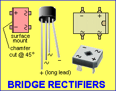
Bridge modules are sometimes hard to identify. The diagrams below show some of the identifications. They are: surface-mount type, W04 (1.5amp bridge), bridge in a chip, and 10amp to 50 amp bridge.
IN-CIRCUIT TESTING
A diode can be tested in-circuit with a multimeter but the reading may be affected by the surrounding components. Lift one end out of circuit to prevent false readings.
<!-- TODO FIXME: add OnHover HoverImage Component here -->
QUESTIONS:
Mouseover the diagram (and keep over) to test the diode.
Determine if the diode is ok and if cathode or anode is on the left.
REMEMBER: Positive voltage comes out the negative lead of an analogue multimeter (from the 1.5v cell or 3v battery inside the multimeter).
<!-- /TODO FIXME: button input -->
<!-- /TODO FIXME: FIX HOVER ON EACH GIF -->
1. State if the diode is ok and identify the lead on the left:
The diode is ok, cathode on left
The diode is ok, anode on left
The diode is faulty - open circuit
The diode is faulty - short circuit
2. State if the diode is ok and identify the lead on the left:
The diode is ok, cathode on left
The diode is ok, anode on left
The diode is faulty - open circuit
The diode is faulty - short circuit
3. State if the diode is ok and identify the lead on the left:
The diode is ok, cathode on left
The diode is ok, anode on left
The diode is faulty - open circuit
The diode is faulty - short circuit
4. State if the diode is ok and identify the lead on the left:
The diode is ok, cathode on left
The diode is ok, anode on left
The diode is faulty - open circuit
The diode is faulty - short circuit
5. State if the diode is ok and identify the lead on the left:
The diode is ok, cathode on left
The diode is ok, anode on left
The diode is faulty - short circuit
The diode is faulty - it is leaky
6. State if the diode is ok and identify the lead on the left:
The diode is ok, cathode on left
The diode is ok, anode on left
The diode is faulty - open circuit
The diode is faulty - short circuit
7. State if the diode is ok and identify the lead on the left:
The diode is ok, cathode on left
The diode is ok, anode on left
The diode is faulty - short circuit
The diode is faulty - it is leaky
8. State if the diode is ok and identify the lead on the left:
The diode is ok, cathode on left
The diode is ok, anode on left
The diode is faulty - open circuit
The diode is faulty - short circuit
9. State if the diode is ok and identify the lead on the left:
The diode is ok, cathode on left
The diode is ok, anode on left
The diode is faulty - open circuit
The diode is faulty - short circuit
10. State if the diode is ok and identify the lead on the left:
The diode is ok, cathode on left
The diode is ok, anode on left
The diode is faulty - open circuit
The diode is faulty - short circuit

Quick Links
Legal Stuff
Social Media