

Table Of Contents
Capacitor Discharge Unit 18,000u kit is available from Talking Electronics for $14.50 plus $6.50 postage.
Click [HERE](mailto:colin@elechelp.com?Subject=Buying capacitor Discharge Unit 18,000u kit $14.50 plus $6.50 postage &Body=Please%20e-mail%20the%20cost%20of Buying capacitor Discharge Unit 18,000u kit $14.50 plus $6.50 postage by%20air%20mail%20to%20my%20country:**___****%20%20and%20send%20details%20of%20how%20I%20can%20pay%20for%20it.%20My%20name%20is:____) for details.
This module is also available fully built and tested for $18.50 plus $6.50 postage**
This is the most powerful unit you can get and it will switch a number of points at the same time.
It has been designed to satisfy all those who want a very powerful unit.
Just because the unit has 18,000u, does not mean it will deliver a higher current than the 2,200u unit. The current will be almost the same, but it will deliver the current for a longer period of time.
In addition, if you have a number of points connected in parallel, they will all get a portion of the energy.
Every model railway has points.
Many of these points are switched remotely due to their distance from the operator or inaccessibility in tunnels etc. Their method of control is usually electrical and up to now a number of problems have been associated with these circuits. They had the tendency to overheat the solenoid and even burn it out if the signal to the solenoid is not switched OFF immediately the point has been changed.
The control of a set of points is simple. Electrical energy is converted to mechanical movement via a solenoid actuator. This device is called a ‘POINT MOTOR.’ They are mounted under or near the point in such a way that the movement sets the blades of the points for one direction or the other.
This involves a linear movement of about 5mm (1/4in). To create this movement, the simplest device is the solenoid. It is simply a coil of wire wound on a former. Inside the former is an iron actuator or armature which can be pulled into the coil when the power is applied. By placing two of these coils end-to-end, a forward and reverse motion can be created. These arrangements are called ‘Switch Machines’ or ‘Point Motors’.
These two-solenoid point-motors are usually switched by short pulses of electricity. The pulse length is often determined by the operator or by a simple spring-loaded switch.
But there are several problems with this arrangement. Point motors require a considerable amount of current for their operation. This means the full capacity of the transformer will be needed. Any other items using the same supply will suffer.
There are other problems too. The high currents will play havoc with switches. The back emf (reverse voltage) generated by the solenoid is sometimes sufficient to weld the switch closed. This will keep the current flowing through the solenoid and it will overheat very quickly.
Our CAPACITOR DISCHARGE UNIT overcomes all these problems.
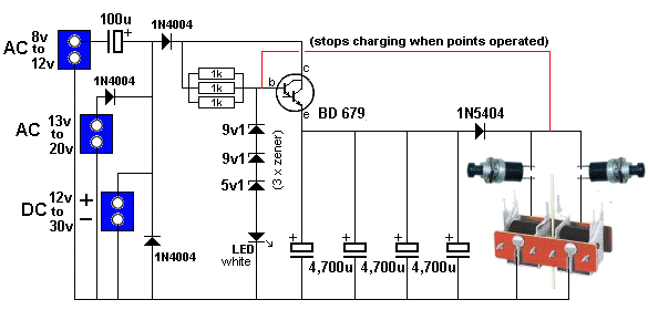
The Capacitor Discharge Unit 18,000u circuit
We have called it 18,000u CDU to identify it from our other Capacitor Discharge Units.
Capacitor Discharge Units (CDU’s) supply a high current ‘burst’ to the solenoid. This current burst is over by the time the switch contacts open, thus eliminating back emf across the switch contacts, Should a solenoid be left in circuit, the current flowing through it (after the initial surge) will be less than 50mA. It won’t even be enough to warm the coil!
THE POWER SUPPLY
The CDU requires an input voltage and this is called THE SUPPLY.
One of the advantages of a CDU is the ability for it to deliver a high current to a point motor to make sure it operates correctly.
A point motor is a solenoid and it has a resistance of less than 5 ohms. This means the current it will draw on 12v is nearly 2.5 amps.
If it is left activated for more than a second, it will get very hot as it is consuming about 30 watts. The CDU prevents this from happening. It only activates a point motor for half a second.
The other advantage of the CDU is it delivers this current from a supply that can be rated at 100mA to 3 amps. If the supply is only capable of 1 amp, it cannot be used reliably to operate the point and a 100mA supply cannot operate the point motor directly.
This project allows a wide range of supplies to be used.
The circuit will accept either an alternating voltage (called AC) or a “battery voltage” (called DC - Direct Current).
It effectively multiplies (increases) the current by charging the capacitors over a long period of time at about 100mA and then provides a current of about 2.5 amps over a shorter period of time.
Since the current required by the CDU is very small, any type of supply from 100mA to 1 amp can be used.
The electrolytics charge-up and store the energy. It is then released in a short burst and this changes the “point.”
Almost all the adaptors you will have in your possession will be the type called DC. However you may have a train transformer with an AC output and this project will accept either.
The project monitors the voltage on the capacitors and prevents it rising above 25.5v by using zener diodes that “remove” the fist 23v and the next 3.2v is used to illuminate a LED and the charging current goes to this LED. This allows a voltage up to 30v to be supplied and the circuit stops the charging when the capacitors reach 26.5v. The voltage drop across the two base-emitter junctions of the Darlington transistor equal 1.4v and when this is subtracted from 26.5v, the result is about 25v. This is theoretically the maximum voltage across the electrolytic after being fully charged.
3 separate inputs are provided and you need to select the correct input so the circuit will charge the capacitors correctly. It converts the voltage if it is AC (to DC) and ceases charging the capacitors when they reach 25.5v.
TYPES OF ADAPTORS
This project needs a minimum supply of about 12v AC or 16v DC and a current of about 100mA.
This means a small power supply can be used and some are rated at 200mA and 500mA.
To get a voltage of 17v, you can use a 5v adapter and 12v adapter and connect the output as shown in the following diagram:

These are two DC adapters
A Plug Pack, Wall Wort or Adapter is the best as it is completely sealed and the output is insulated and isolated from the mains.
These are cheaper than making your own power supply and you can use some of your (discarded) 5v adapters from your old-model phones. You can connect three to get 15v.
Make sure the wiring is connected so the voltages are ADDED to the output. Even 300mA, 500mA and 1 amp adapters can be connected as we are only requiring 200mA.
You can do the same with AC adapters and although the output is changing many times a second, the output wires have to be connected so they ADD to the output. Connecting them the wrong way with produce ZERO output.
You can connect adapters of different voltages and current and even AC and DC adapters as the circuit will accept all these variations. You can connect an AC adapter either way around to a DC adapter and it will produce AC of the combined voltage for the first half-cycle and zero voltage for the second half-cycle.
This is a good project to use-up those discarded adapters.

The top view of the 18,000u CDU

The front view of the 18,000u CDU

The output of the 18,000u CDU

The 3 different inputs for the 18,000u CDU

The four 4,700u electrolytics standing up to show the components on the 18,000u CDU module.
OVER-VOLTAGE
We have suggested using a 24v plug pack or a 12v and 12v or 12v and 5v.
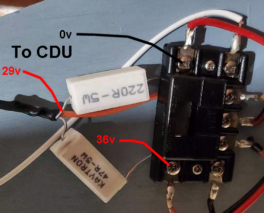
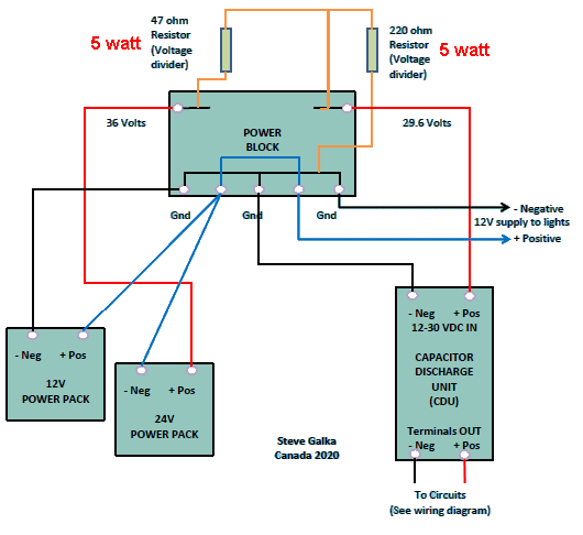
One customer used a 24v and 12v and although the regulator zeners delivered 26.5v to the electrolytics, the zeners got quite hot. This is because the voltage above 26.5v and 32v appears across the 330R resistors (3 x 1k) and extra current flows through the resistors. This extra voltage is about 5v and the current is about 15mA. This current flows through the zeners and 5v1 zener will dissipate 75mW and the 9v1 zeners will dissipate about 135mW.
If you want to reduce the heat, a voltage divider can be added to the input of the CDU.
Here is a solution from a customer Steve Galka:
He added a 220R and 47R wire wound resistors in series (5 watt types) and across the 220R he got 29.5v
Here is his addition and the circuit:
HOW DOES IT WORK?
This project has 3 features.
- It provides 3 different types of supply.
- It indicates when the capacitors are fully charged.
- It prevents the capacitors over-charging.
The DC input is passed directly to the circuit via a diode. Current flows at a rate determined by the ability of the supply. As the capacitors charge, the current reduces until it is less than 50mA and this current is passed through the LED to illuminate it.
There are two AC inputs. If the AC voltage is between 13v and 20v, it passes through a diode so that only the positive half-cycles are passed to the capacitors. This is called half-wave charging.
If the voltage is 8v to 12v, the AC is connected to a voltage-doubling arrangement consisting of a 100u electrolytic and a diode.
Recharge time depends on the supply voltage and will be only a few seconds.
The high-current output diode allows a high current to flow to the solenoid and while the switch is pressed, the circuit is prevented from charging the electrolytics because the output is connected to the base of the transistor. When the switch is released, the output is allowed to go high via the three 330R resistors because the diode is reverse biased. This allows the capacitors to be charged.
CONSTRUCTION
Assembly of the PC board is straightforward. Three 1k 1/4watt resistors are wired in parallel to form a single resistor.
All the other components are clearly marked on the board and you must pay attention to make sure they are around the correct way.
PARTS LIST
$14.50 plus $6.50 postage.
Click [HERE](mailto:colin@elechelp.com?Subject=Buying capacitor Discharge Unit 18,000u kit $14.50 plus $6.50 postage &Body=Please%20e-mail%20the%20cost%20of Buying capacitor Discharge Unit 18,000u kit $14.50 plus $6.50 postage by%20air%20mail%20to%20my%20country:**___****%20%20and%20send%20details%20of%20how%20I%20can%20pay%20for%20it.%20My%20name%20is:____) for details**
- 3 - 1k
- 1 - 100u 25v electrolytic
- 4 - 4,700u 25v - 35v. see text
- 1 - 5v1 400mW zener diode
- 2 - 9v1 400mW zener diodes
- 3 - 1N 4004 1-amp diodes
- 1 - 1N5404 3-amp diode
- 1 - 3mm white or blue LED
- 1 - BD 679 Darlington transistor
- 1 - 2-screw terminal blocks
- 2 - 3-screw terminal blocks
- 1 - 20cm fine solder
- 1 - CDU 18,000u PC Board
CONNECTING THE UNIT
Disconnect the wires going to the point motor, from the transformer, and connect them to the input of the CDU.
Connect the output of the CDU to two switches as shown in the diagram below. Connect the other pins of the switches to the point motor. It is now ready.
When the power is applied, the white LED will come on after a few seconds.
The LED can be placed on the main control panel of the layout to indicate the condition of the unit. The LED will light to indicate when the unit is ready. When a point is operated, the LED will extinguish, then come back on when the capacitor charges. If it remains extinguished, it indicates a fault is present and the solenoid may be still in circuit. No other points can be operated until this is fixed, but at least the solenoids will not be damaged!
Note: Train transformers often have an output of 15v to 16v when labelled 12v, so this must be taken into account. (They drop to 12v on full load).
12v DC is the absolute minimum and may not work very well because the components on the module drop the incoming voltage by a few volts.
If it does not work, try a higher voltage.
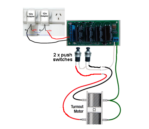
Wiring the Capacitor Discharge Unit 18,000u to the Point Motor

Quick Links
Legal Stuff
Social Media